Section 3: Unpacking and Installation FC-3800 Facility and Installation Guide
FC-3800 F & I Guide
3-4
0101-8604-0, Rev. F
locked in that position until the system is ready to be energized by (or under the
supervision of) the Temescal service representative.
NOTE: Do NOT energize the system or any of its components at this time.
3.2.5 Installing the E-Beam Power Supply
Regardless of which power supply the system uses, install power Drop #2 and connect it
to the power distribution box, but do not connect the HV power supply to that drop. The
Temescal representative will oversee the connection of that power supply to Drop #2. If
the system is equipped with a Simba 2 power supply, locate the Simba 2 power module
approximately as shown in Figure 3-2.
NOTE
Do not place the gun interface module directly on top of the
Simba 2 power module. If the gun interface is not mounted in the
optional control console available with the Simba 2 power supply,
it should be mounted in the operator station. The optional Simba
2 control console (containing the gun interface) can be placed on
top of the power module
3.2.6 Installing the Mechanical Pump
With the vacuum cubicle in place and leveled within specifications, install the mechanical
pump (with blower, if this option is included in your system) and install and connect the
roughing line and the mechanical pump exhaust. To do so:
1. Loosen the clamps connecting the flexible hose to the mechanical pump.
2. Release the bolts that hold the mechanical pump to the system frame during
shipment, allowing the pump to rest on the floor.
3. Retighten the clamps on the flexible hose to isolate the vacuum cubicle from the
pump’s vibration.
4. Remove the blank flange from the roughing port.
5. Install the roughing pump and blower, if included in the system.
6. Check the oil level in the mechanical pump and the blower, if any.
Note: Electrical connections to the mechanical pump must be made by the Temescal
service representative.
3.2.7 Making Service Connections
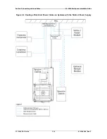
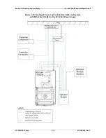
The customer is responsible for providing the utility lines specified below and for
connecting these lines at the facility end. The customer may lay out these service lines so
they are properly routed all the way to their connection points at the system (see Figures
3-4 and 3-5). However, service connections to the system may be made only by or under
the supervision of a Temescal service representative, unless the customer has made
specific arrangements to the contrary.
Water:
Cold water supply #1: Vacuum cubicle water
Optional hot water supply for vacuum cubicle
Cold water supply #2: Cryopump compressors
Cold water supply #3: Required only on systems with water-cooled mechanical
pumps


