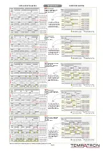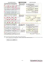
Press the key together with the key to enter the programming menu.
To Exit Programming Mode
When in programming mode if no key is pressed for 20 seconds, the parameter settings are stored and the timer reverts to operation mode.
Alternatively to exit programming mode press the key and key together
, the parameter settings are stored and the timer reverts to operation mode.
9 dif
ferent time periods can
be selected (see
Table 1). If
this parameter is changed,
and are changed automatically
.
9 dif
ferent time periods can be
selected (see
Table 1). If this
parameter is changed, and are changed automatically
.
Timer 1 setpoint lower limit can be adjusted between 0 and the parameter value.
Timer 1A
setpoint lower limit can
be adjusted between 0 and the parameter value.
Timer 1 setpoint upper limit can be adjusted between the and parameter values.
Timer 1A
setpoint upper limit can
be adjusted between the and parameter values.
This menu is displayed only if parameter is set to , or ‘Out Mode b’
is selected.
9 dif
ferent time periods can
be selected (see
Table 1). If
this parameter is changed,
and are changed automatically
.
9 dif
ferent time periods can be
selected (see
Table 1). If this
parameter is changed, and are changed automatically
.
Timer 2 setpoint lower limit can be adjusted between 0 and the parameter value.
Timer 1A
setpoint lower limit can
be adjusted between 0 and the parameter value.
Timer 2 setpoint upper limit can be adjusted between the and parameter values.
Timer 2A
setpoint upper limit can
be adjusted between the and parameter values.
13 dif
ferent timing output modes
can be selected (see timing mode diagrams on pages 5-7 for details).
Set output 1 to either or (for output 1 setting requirements see timing mode diagrams on pages 5-7 for details).
Set output 2 to or
(for output 2 setting requirements see timing mode diagrams on pages 5-7 for details).
Set to for output to be continuously activated. Alternatively set between 0.01 and 99.99 seconds (for output 1 setting requirements see timing mode diagrams on pages 5-7 for details).
Set to for output to be continuously activated. Alternatively set between 0.01 and 99.99 seconds (for output 2 setting requirements see timing mode diagrams on pages 5-7 for details).
If set to the timer count position and output contact status will not be retained upon loss of power to the timer
. If
set to the timer count position will be retained upon loss of power to the timer and the timer will continue from where it stopped once power is restored.
Set to for the timer to count upwards or set to for the timer to count downwards.
0.001, 0.020, 0.050 and 0.100 second values can be selected. Pulse and void durations for the start, gate and reset inputs must be greater that the set value.
Set the input type for the Start, Gate and Input to either or .
The display brightness can be set between 1 and 20.
Set which parameters are to be displayed on the top and bottom displays (see
Table 2 for options).
Note:
This setting resets to
when and parameters are changed so will need re-adjusting if necessary
.
If set to the reset key will not function. If set to the timer can be reset by pressing the reset key for 1 second.
To access this menu enter the security code 4400.
Press the key together with the key for 4 seconds. is displayed and the timer is returned to factory default settings.
To Fully Reset The T
imer
Parameter menus not accessible
Parameters can be modified
Parameters can be viewed only
Parameter menus not accessible
Parameters can be modified
Parameters can be viewed only
Parameter menus not accessible
Parameters can be modified
Parameters can be viewed only
Parameter menus not accessible
Parameters can be modified
Parameters can be viewed only
Depending on how parameters and are set some display modes may not be displayed.
Between
0.01 sec and 99.99 sec
Between
0.1 sec and 999.9 sec
Between
1 sec and 9999 sec
Between
0 min 1 sec and 99 min 59 sec
Between
0.1 min and 999.9 min
Between
1 min and 9999 min
Between
0 hours 1 min and 99 hours 59 min
Between
0.1 hour and 999.9 hours
Between
1 hour and 9999 hours
Table 1
Time Range Selection
Table 2
Display Parameter Selection
Timer 1
Timer 1
Timer 1
Timer 1
Timer 2
Timer 2
Timer 1
T1 set
T1A
set
T2 set
T2A
set
T2 set
T2A
set
Timer 2
To set a parameter value hold down the key and the whole or part of the selected parameter will flash.
Adjust
the value using the or keys until the desired value is reached. Hold the key and then press the
key and the next part of the selected parameter will now flash and can be adjusted in the same way
.
If the or key is held for more than 1 second the value of the selected digits changes more rapidly
.
PROGRAMMING MODE
Stores the parameter settings and the timer reverts to operation mode
How to
Adjust a Parameter
Page 4


