background image

9

Auto-tuning 

The auto-tuning process is performed near the set point. The process 
will oscillate around the set point during the tuning process. Set the 
set point at a lower value if overshooting beyond the normal process 
value is likely to cause damage. 

Auto-tuning is applied in cases of:


• 

Initial setup for a new process 

• 

The set point is changed substantially from the previous  
auto-tuning value 

• 

The control result is unsatisfactory 

Operation: 

1.  The system has been installed normally. 

2.  Set the correct values for the setup menu of the unit, but don’t 

set a zero value for PB and TI, or the auto-tuning program will 
be disabled. The LOCK parameter should be set at NONE. 

3.  Set the set point to a normal operating value, or a lower value if 

overshooting beyond the normal process value is likely to cause 
damage. 

4.  Press 

 and hold until 

 appears on the display. 

5.  Then press 

 again for at least 5 seconds. The AT indicator will 

begin to flash and the auto-tuning procedure begins. 

NOTE: 

The ramping function, if used, will be disabled when  

auto-tuning is taking place. 

Auto-tuning mode is disabled as soon as either failure mode or 
manual control mode is entered. 

Procedures: 

Auto-tuning can be applied either as the process is warming up 
(cold start), or when the process has been in a steady state (warm 
start). After the auto-tuning procedures are completed, the AT 
indicator will cease to flash and the unit will revert to PID control 
using its new PID values. The PID values obtained are stored in 
the nonvolatile memory. 

 Auto-Tuning Error 

If auto-tuning fails an ATER message will appear on the upper 
display in the following cases: 

• If PB exceeds 9000 (9000 PU, 900.0°F or 500.0°C), 

• if TI exceeds 1000 seconds, 

• if the set point is changed during the auto-tuning procedure. 

Solutions to


1. Try auto-tuning once again. 

2. Don’t change the set point value during the auto-tuning procedure. 

3. Don’t set a zero value for PB and TI. 

4. Use manual tuning instead of auto-tuning (see section 3-12). 

5. Touch RESET key to reset 

 message. 

Manual Tuning 

In certain applications auto-tuning may be inadequate for the 
control requirements. You can try manual tuning for these 
applications. 

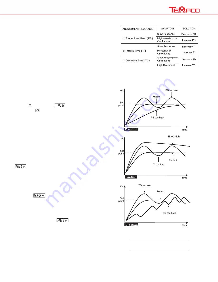
If the control performance using auto-tuning is still unsatisfactory, 
the following rules can be applied for further adjustment of PID 
values:

Figure 3.9 shows the effects of PID  

adjustment on process response.

Figure 3.9  Effects of PID Adjustment

Table 3.2  PID Adjustment Guide

Summary of Contents for TEC-9100

Page 1: ... within this console Power to all equipment must be disconnected before installation or beginning any troubleshooting procedures Heater output wiring and component replacement must be made by qualified personnel only 3 To minimize the possibility of fire or shock do not expose this console to rain or excessive moisture 4 Do not use this console in areas where hazardous conditions exist such as exc...

Page 2: ... ABC 1 R Used for TEC 9100 Controller EHD 124 290 for 4 zone units Fuse 1 rated 1 5 Amp 250V x 1 slow acting BUSS ABC 1 5 R Used for TEC 9100 Controller EHD 124 300 for 2 zone units Fuses 2 rated 8 amps 250V x 1 fast acting BUSS ABC 8 R EHD 124 279 for 3 zone units Fuses 3 rated 5A 250V x 1 fast acting BUSS ABC 5 R EHD 124 282 for 4 zone units Fuses 4 rated 4 amps 250V x 1 fast acting BUSS ABC 4 R...

Page 3: ...ow cost enhanced reliability and higher density Fast sampling rate The sampling rate of the input A to D converter is 5 times second The fast sampling rate allows this series to control fast processes Fuzzy control The function of Fuzzy control is to adjust PID parameters from time to time in order to make manipulation of the output value more flexible and adaptive to various processes The result ...

Page 4: ...well timer has timed out 6 Enter the manual control menu when in failure mode ENTER KEY Press for 5 seconds or longer Press for 5 seconds to 1 Enter setup menu The display shows 2 Enter manual control mode when manual control mode is selected 3 Enter auto tuning mode when auto tuning mode is selected 4 Perform calibration to a selected parameter during the calibration procedure Press for 6 2 secon...

Page 5: ...5 1 5 Menu Overview ...

Page 6: ...t shown in the above table NOTE It is strongly recommended that a process should incorporate a LIMIT CONTROL such as the TEC 910 which will shut down the equipment at a preset process condition in order to preclude possible damage to products or system Information in this user s manual is subject to change without notice ...

Page 7: ...en all setup data as well as user data refer to section 1 5 except the set point are locked to prevent them from being changed If ALL is selected for LOCK then all parameters are locked to prevent them from being changed 3 2 Signal Input INPT Selects the sensor type or signal type for signal input Range thermocouple J TC K TC T TC E TC B TC R TC S TC N TC L TC RTD PT DN PT JS Linear 4 20mA 0 20mA ...

Page 8: ...lagged filtered signal if used for control may produce an unstable process The controller will enter failure mode if one of the following conditions occurs 1 SBER occurs due to input sensor break or input current below 1mA if 4 20 mA is selected or input voltage below 0 25V if 1 5V is selected 2 ADER occurs due to the A D converter of the controller failing Output 1 and output 2 will perform the f...

Page 9: ...e mode or manual control mode is entered Procedures Auto tuning can be applied either as the process is warming up cold start or when the process has been in a steady state warm start After the auto tuning procedures are completed the AT indicator will cease to flash and the unit will revert to PID control using its new PID values The PID values obtained are stored in the nonvolatile memory Auto T...

Page 10: ...10 Table A 1 Error Codes and Corrective Actions ...

Page 11: ... compliance with any applicable specification TEC Temperature Controllers are warranted to be free from defects in material and workmanship for two 2 years after delivery to the first purchaser for use Tempco s sole responsibility under this warranty at Tempco s option is limited to replacement or repair free of charge or refund of purchase price within the warranty period specified This warranty ...

Page 12: ...le Heaters Process Heaters Temperature Control Cartridge Heaters Coil Cable Heaters Strip Heaters Tubular Heaters Instrumentation Temperature Sensors HEAT THINGS UP HEAT THINGS UP With Thousands of Design Variations We Make Everything You Need Custom Manufacturer Since 1972 ELECTRIC HEATING ELEMENTS TEMPERATURE CONTROLS SENSORS PROCESS HEATING SYSTEMS Copyright 2020 All Rights Reserved ...

Reviews: