- 3 -
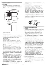
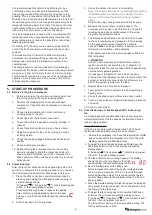
Figure 3. Pressurisation bung locations
4. CONTROLS
4.1 Electrical Requirements
Electrical work must be done by a qualified electrician.
DANGER! LIVE ELECTRICAL CONNECTIONS. DISCONNECT MAINS
POWER BEFORE WORKING ON UNIT. ONLY QUALIFIED PERSONS
WHO ARE COMPETENTLY TRAINED SHOULD PERFORM SERVICE AND
MAINTENANCE TASKS.
The outdoor unit must be wired directly from a distribution
board by means of a circuit breaker and a mains isolator
provided – preferably close to the unit.
A 24 hour power supply to the compressor crank case
heaters is required, otherwise the warranty is void.
4.2 Control options
OPA Econex units can be controlled using any of the
following options:
• TZT-100 wall thermostat
• SAT-3 wall thermostat
• 24V AC and 0-10V signals from an external controller or
thermostat
• Remote on/off switch and/or time clock
• Modbus RTU serial communications over RS485
connection
• BACnet-IP serial communications over Ethernet
connection (with optional gateway module)
Standard reverse cycle units are suitable for use with
thermostats and controls with manual heating/cooling
selection or automatic change-over.
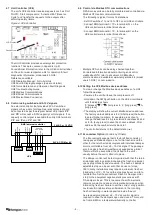
A unit wiring diagram is supplied alongside the electrical
board and in the Specifications document.
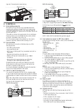
4.3 TZT-100 or SAT-3 wall thermostat
To connect the thermostat to the unit it is recommended
to use shielded twisted pair type cable, suitable for RS485
communications. Signals A and B should form one twisted
pair.
Note: The cable shield should connect to terminal ‘0V’ on
the UC8 controller only. Do not connect at both ends.
Connect the thermostat as follows:
TZT-100 Connection:
TB5
B1
TB6
A1
TB7
0V
TB8
12V
TB9
B
A
24C
24
W6
PCLP1
TZT-100
OPA
TB5
B1
TB6
A1
TB7
0V
TB8
12V
TB9
B
A
GRND
12V
W6
PCLP1
SAT-3
OPA
Control
- shielded
twin twisted pair
4 core
(201-000-399)
Control
- shielded
twin twisted pair
4 core
(201-000-399)
SAT-3 Connection:
TB5
B1
TB6
A1
TB7
0V
TB8
12V
TB9
B
A
24C
24
W6
PCLP1
TZT-100
OPA
TB5
B1
TB6
A1
TB7
0V
TB8
12V
TB9
B
A
GRND
12V
W6
PCLP1
SAT-3
OPA
Control
- shielded
twin twisted pair
4 core
(201-000-399)
Control
- shielded
twin twisted pair
4 core
(201-000-399)
Note: Capacity Staging. A TZT-100 or SAT-3 must be
configured for single-stage operation, the default setting.
TZT-100 has its own DIP switches that must be set as
follows:
DIP switch 2
ON
Equipment type = Heat Pump
DIP switch 3
OFF Equipment stages = One
DIP switch 4
ON
Reverse cycle valve on = Heating
SAT-3: Refer SAT-3 Installation Set-up Guide page 3.
4.4 Communications format for TZT-100 and SAT-3
Communications format must be set as per recommended
Modbus RTU:
• Baud rate (bd or br) 19200
• Data bits
8
• Parity
Even
• Stop bits (Pa)
1
• TZT-100 address (Ad) 7
• SAT-3 address (Ad) 8
TZT-100:
The procedure to check and adjust these settings is:
1. Press and hold the O/RIDE button until the display
shows the PIN
2. Use the UP & DOWN buttons to select PIN code 88:21,
then press O/RIDE in installer mode.
3. Use the O/RIDE and PROG buttons to cycle through the
various installer settings.
If necessary, refer TZT-100 User Manual for more detail.
SAT-3:
The procedure to check and adjust these settings is:
1. Press and hold the MODE and 6 button until the display
shows the ‘i’ symbol.
2. Use the UP & DOWN buttons to cycle through the
various installer settings.
3. Press MODE button to save any new setting.
If necessary, refer SAT-3 Installation Set-up Guide for more
detail.
4.5 Remote on/off
The UC8 has an input for a remote on/off function on
terminal ‘On’, signal return is terminal ‘0V’. When used the
remote on/off terminals should connect to a voltage-free
relay contact. When not used the remote on/off terminals
should be shorted (‘bridged’).
4.6 Capacity control
OPA Econex units offer the following capacity control
options:
• Automatic control when the unit connects to the TZT-100
or SAT-3 wall thermostat.
• 0-10V compressor control signal
• 0-10V indoor fan control signal.
• Control by a building management system via Modbus
RTU or BACnet-IP serial communications.
Drawn:
Title:
Drawing No:
23/02/2022
pchandrasekaran
A
Rev:
Date:
©temperzone Ltd 2021
OPA 560 RLTFPQ-CZ (01, 10, 23, 32)
OPA 560 RLTFPQ-CZ Combined Variants
876-056-700
Est Weight:
0 kg
Sheet 1 of 1
*876-056-700/A*
3rd ANGLE PROJECTION
Do not scale drawing
Interpret drawing as per GD&T standard: ISO 2768-1
Unless specified all dimensions are in millimeters
Mat:
Fin:
PROPRIETARY & CONFIDENTIAL
The information contained in
this drawing is the sole
proprietary of temperzone limited.
Unauthorised copying,
possession, discussion, publication
& distribution prohibited
TOLERANCES UNLESS STATED
LINEAR: ANGULAR:
0 = ±0.5 0 = ±1°
0.0 = ±0.1 0.0 = ±0.5°
0.00 = ±0.05 0.00 = ±0.1°
Standard hand unit
Opposite hand unit


