Temperzone SAT-‐3 Installation Setup Guide, Issue 2
Page 5
of 7
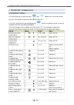
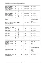
Notes:
1.
Auto cool/heat mode can only be enabled if both cooling and heating mode are also
enabled.
2.
Dry mode (de-‐humidification) can only be enabled if cooling mode is also enabled.
3.
Room temperature sensor: 1 = internal, 2 = external, 3 = average of internal and
external, 4=zone 1 temperature (from modbus – do not use with un-‐zoned systems).
4.
Zone 1 temperature calibration is applied to the room temperature from the
selected source described above in note 3.
5.
Programmable timer function: 1 = standard, 2 = advanced.
6.
Not applicable to systems without zone controller.
2.2.
Fan Settings
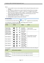
To activate fan setup mode hold down
and
together for 3 seconds. When
Fan Setup Mode is active the symbol
on the display flashes on and off.
Settings in Fan Setup Mode are as follows:
Setting
Display
Range
Notes
Low level fan
control voltage
SET
Lo
2.0 to 8.0
Default 5.0
High level fan
control voltage
SET
Hi
4.0 to 10.0
Default 8.0
Steps of 0.333
e.g. 2.0, 2.3, 2.7, 3.0, etc.
Additional zone
voltage increase
SET
Ad
0 to 950
Default 300
Zone 1 balance
bL
10 to 100%
Default 100%
Zone 2 balance
bL
10 to 100%
Default 100%
Zone 3 balance
bL
10 to 100%
Default 100%
Zone 4 balance
bL
10 to 100%
Default 100%
Zone 5 balance
bL
10 to 100%
Default 100%
Zone 6 balance
bL
10 to 100%
Default 100%
Not applicable to systems
without zone controller
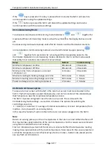
As the settings are adjusted the unit controller adjusts its operation to allow the settings to
be evaluated:
Setting
Unit controller operation
Low level
control voltage
The indoor fan operates at the low voltage level selected
High level
control voltage
The indoor fan operates at the high voltage level selected


