background image

TEMPEST MVU Operation Manual                            


Copyright 2005, Tempest Technology Corporation 
 

24 

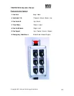
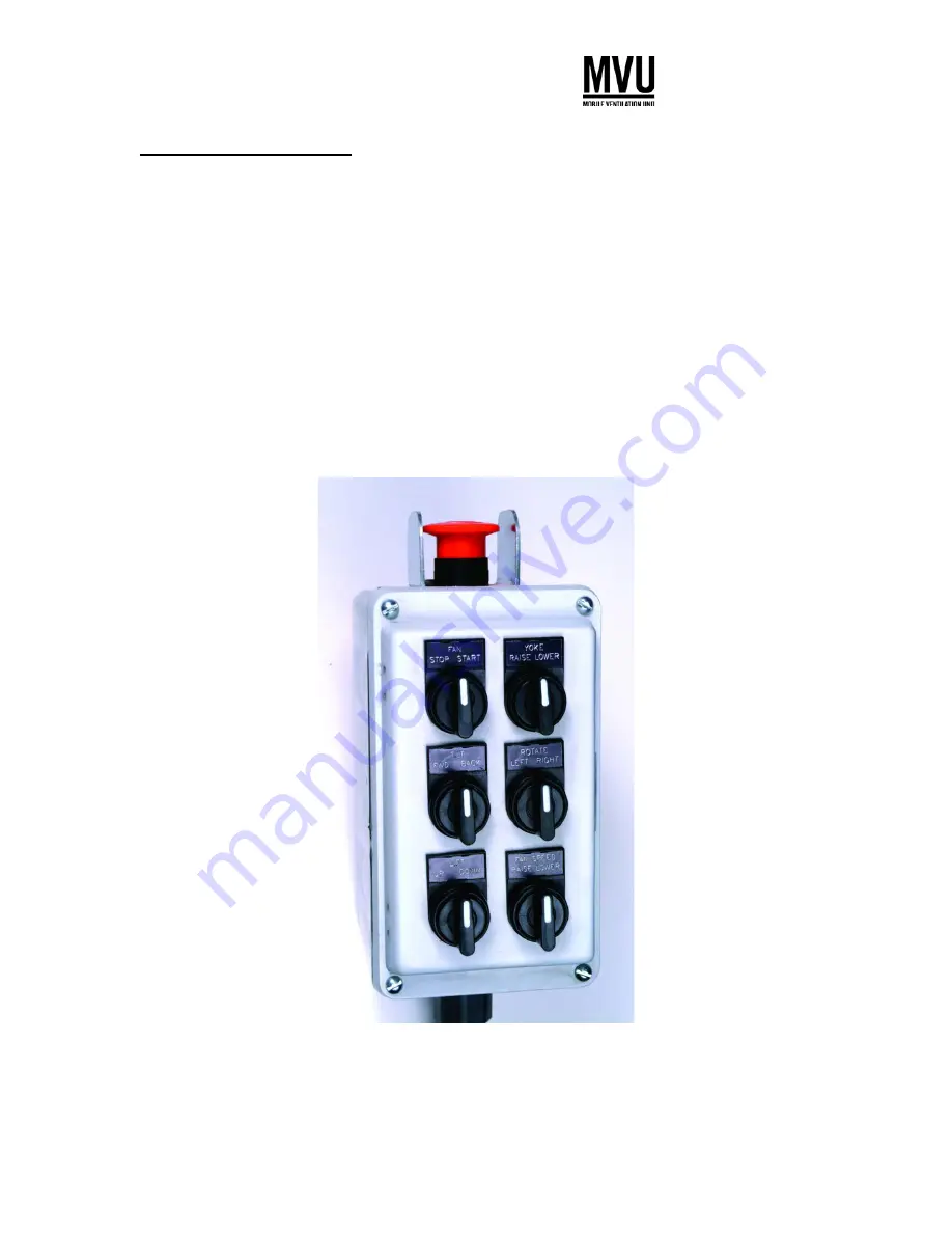
Remote Control System 

 
1 Fan Unit 
 
2 Ventilator Tilt 
 
3 Fan Unit Lift 
 
3 Yoke Raise 
 
4 Fan Unit Rotate 
 
5 Fan Speed 
 
6 Emergency Shut-Down 


Stop / Start 
 

Forward = Down / Back = Up 
 

 Up / Down 
 

Raise / Lower 
 

 Right / Left 


 Up = Faster / Down = Slower 


Shuts Down Diesel Engine 


Summary of Contents for MVU-48

Page 1: ...tion Unit Operation Manual For Additional Information contact Tempest Technology Corporation 4708 N Blythe Ave Fresno CA 93722 Tel 559 277 7577 Fax 559 277 7579 Email response tempest us com Internet www tempest us com ...

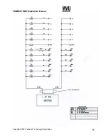
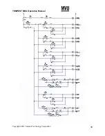
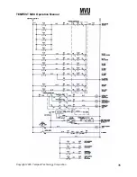
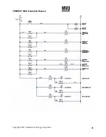
Page 2: ... Specifications 15 MVU Misting System 18 Control Panel Features and Operation 19 Remote Control System 24 Ventilator Bracket and Lowering System Operation 25 Starting and Stopping Instructions 26 MVU Maintenance Schedule 27 MVU Troubleshooting Guide 29 Spare Parts List 31 Electrical Wiring Diagrams 32 Hydraulic System Diagrams 39 Murphy Display and Diagnostic Module 43 ...

Page 3: ...ve the right to make any changes or improvements that we consider to be appropriate Any obligation to earlier delivered models shall not be connected herewith Copyright 2005 by Tempest Technology Inc 4708 N Blythe Ave Fresno CA 93722 USA Contents TD Technical Documentation Formation TD Technical Documentation Duplication of these operating instructions by printing photocopy electronic data exchang...

Page 4: ...erating instructions contain the descriptions for operation maintenance and replacement parts Before you put the MVU into service take the time to thoroughly read this manual to familiarize yourself with it Diesel Engine Operation Operation and maintenance of the diesel engine see engine manufacturer s manual ...

Page 5: ...ions and or images If your device should be equipped with different equipment that is not itemized or described in these operating instructions please notify Tempest Technology You will be informed by our technical staff about the correct operation and maintenance Images All images as well as mass and technical data in these operating instructions are non binding The operating instructions are an ...

Page 6: ...oid injury or damage to the MVU The Mobile Ventilation Unit is constructed with the latest state of the art technology and safety features Nevertheless it can be dangerous for the user if not operated properly The MVU may only be serviced by personnel who have been properly trained in the hydraulic and operating systems maintenance Ongoing training with the MVU as well as education through special...

Page 7: ...marked with this sign It means that injury potential exists Follow all security warnings as well as the accident prevention instructions Meaning Indicated to prevent personnel or extensive property damages The place with the highest danger warning marks Special statement to prevent property damage and promote general cautious measures Statement with respect to the economic use of the device as wel...

Page 8: ...el Exhaust Fumes Carry operator ear protection with the motor and ventilator The diesel engine which powers the hydraulic system emits poisonous exhaust fumes Exhaust fumes can cause severe health damage Do not operate the ventilator in a closed unventilated room Dangerous exposure to carbon monoxide CO can result ...

Page 9: ...y when the motor is turned off No smoking Do not refuel the MVU in a closed room The fumes are poisonous and explosive Always clean up spilled fuel Be especially careful of sparks open flame large heat radiation etc Only operate the ventilator if all protection devices are in place Before removing the protection devices disengage the motor and drives as well as disconnect the ignition power ...

Page 10: ...amination incidents wear appropriate safety clothing When operating the ventilator always pay attention to maximum allowable motor speed and ventilator RPM Observe the gauges for the oil and temperature while operating the MVU Sufficiently illuminate and protect the gauges and warning indicators Maintenance and service should only be conducted by persons who are properly trained and know the safet...

Page 11: ...t be operated in an explosive environment Work on the electrical system may only be performed by an electrician or by trained personnel under the direction and supervision of an electrician in accordance with proper guidelines and procedures When working on the electrical system disconnect the cable of the negative terminal of the battery When connecting of the battery first install the cable to t...

Page 12: ... load of the battery emerges a highly explosive gas mixture Fire spark open light and smoke are forbidden Avoid any spark sources when working with the cable and electric devices Avoid short circuits Personnel Warning Battery acid is extremely corrosive therefore Wear hand protection Wear eye protection Do not tilt the battery acid can spill out of the opening An unloaded battery can freeze theref...

Page 13: ...essories that do not come from Tempest Technology Inc or are not tested and approved by Tempest can adversely affect the durability and performance characteristics of the MVU and affect operator safety Recycle oils fuel battery and filters in accordance with the legal and environmental rules Never dispose of in water or rivers Store used fluids only in approved containers Before throwing away a pa...

Page 14: ...Tempest Technology Corporation 14 Maintenance Support and Service If problems occur during the maintenance and service of the ventilator please contact Tempest Technology Inc 4708 N Blythe Ave Fresno CA 93722 USA Tel 559 277 7577 Fax 559 277 7579 ...

Page 15: ... Hook Skid Only Total Height 105 inches Total Width 91 inches Total Length 175 inches Total Weight 10 950 pounds Blower Assembly Shroud Diameter 48 inches Shroud Material Steel Impeller 7 blades aluminum Blower Performance Volume of air 80 000 CFM 130 000 Effective CFM 380 000 CFM nominal open airflow Velocity of air stream at outlet 70 MPH Fan Adjustment Scissors Lift 118 max lift Tilt up 45 Tilt...

Page 16: ...3 gallons minute 2 900 psi Yoke Raise Lower Hydraulic cylinder to lift Gravity return to lower Fan Rotation 24V Electric Motor Control Systems Electric and Electric over Hydraulic Fixed Panel with controls Engine fan RPM Gauges for temperature oil pressure Panel light Engine hour meter Emergency shut down switch Fan lift tilt and rotation Lowering System raise lower Remote Control Portable control...

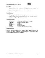
Page 17: ...along both sides and end of the platform Acoustic warning during lowering of fan unit Water Mist System Misting Ring 1 5 diameter stainless steel 8 nozzles Flow Rate 87 gallons minute 100 psi Reach 130 feet Droplet Size 200 microns Supply Central duct system Coupling 1 5 hose coupling with shut off valve Lowering System Hydraulic lowering mechanism for the fan unit to reduce the overall height of ...

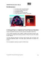
Page 18: ...ounted forward of the propeller inside the ventilator shroud A total of eight evenly spaced 65 degree spray pattern nozzles on the ring provide a homogenous water fog The air stream generated by the ventilator is utilized to transport the water vapor At a flow rate of 74 gpm and a delivery pressure of 105 psi the reach of the stream is over 100 feet The finely dispersed droplets of the water vapor...

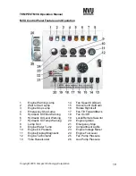
Page 19: ...t 4 Emergency Stop Lamp 17 Fan Tilt Forward Back 5 Hydraulic Oil Filter Warning 18 Fan On Off 6 Hydraulic Oil Level Warning 19 Local Remote Selector 7 Hydraulic Oil Temp Warning 20 Engine Ignition 8 Lamp Test 21 Emergency Stop 9 Engine Water Temp 22 Compartment Lights 10 Engine Oil Pressure 23 Engine Voltage Meter 11 Engine Display Diagnostic 24 Engine Fuel Level 12 Engine Tachometer 25 Fan Pump P...

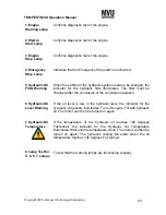
Page 20: ...lic system needs to be changed the indicator for the hydraulic filter illuminates The filter must be changed after the conclusion of the ventilation operation If the oil level is low in the hydraulic tank the indicator for the hydraulic oil quantity illuminates Turn off engine Fill with hydraulic oil The motor can then be turned on again If the temperature of the hydraulic oil reaches 190 degrees ...

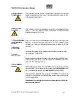
Page 21: ...y and Diagnostic Module It provides Engine data such as hours RPM system voltage etc See the operating instructions on page 46 of this manual Indicates the speed of the diesel engine Maximum speed with fan running is 1 450 RPM Used to raise and lower the yoke Turn the switch to RAISE and hold until the yoke stops Turn the switch to LOWER to lower the yoke into the nesting position After starting t...

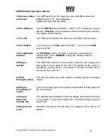
Page 22: ...tilt fan down To turn fan on turn FAN switch to START To turn off turn FAN switch to STOP Set CONTROL switch to LOCAL if using the control panel to operate MVU Set to REMOTE if using the remote control to operate the MVU Turn IGNITION switch to ACC position Wait for red orange and blue system check lights to turn off The starting of the motor is actuated by turning the key to the right The motor i...

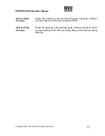
Page 23: ...Pump Pressure 26 Aux Pump Pressure Shows the pressure in the fan pump Pressure should be 1 250 psi at engine idle and 3 000 psi at maximum RPM Shows the pressure in the auxiliary pump Pressure should be 2 000 psi during tilting 800 1 350 psi during lifting and 2 000 psi during lowering ...

Page 24: ...ogy Corporation 24 Remote Control System 1 Fan Unit 2 Ventilator Tilt 3 Fan Unit Lift 3 Yoke Raise 4 Fan Unit Rotate 5 Fan Speed 6 Emergency Shut Down Stop Start Forward Down Back Up Up Down Raise Lower Right Left Up Faster Down Slower Shuts Down Diesel Engine ...

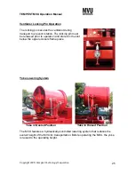
Page 25: ...rotation The locking pin must be released prior to operation and stored in the slot below the upper scissors frame piece Yoke Lowering System Yoke in Nested Position Yoke in Raised Position The MVU features a hydraulically controlled lowering system that reduces the overall height of the MVU for transportation Before operating the MVU the yoke is raised to the operating height ...

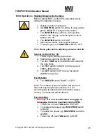
Page 26: ...ift and Fan Tilt 1 Follow engine starting instructions 2 Start engine and idle at 700 1000 rpm 3 Turn the YOKE switch to RAISE and hold until the yoke stops 4 Turn TILT switch to BACK to tilt fan up and FWD to tilt fan down 5 Turn LIFT switch to UP to raise fan and to DOWN to lower fan Fan Rotation 6 Turn ROTATE switch RIGHT or LEFT Note The rotation system is 24vDC powered and does not require hy...

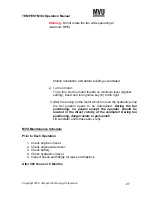
Page 27: ... the turning on the motor which turns on the hydraulic pump the fan position needs to be determined During the fan positioning no people except the operator should be located in the direct vicinity of the ventilator During fan positioning danger exists to personnel Lift ventilator until stroke above 24 MVU Maintenance Schedule Prior to Each Operation 1 Check engine oil level 2 Check engine water l...

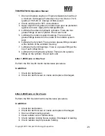
Page 28: ...6 Lubricate the fan shaft There are two grease fittings located at the bottom of the ventilator housing 7 Lubricate the fan tilt bearings There is a grease fitting at the top of each pillow block 8 Lubricate the tilt hydraulic cylinder There are two grease fittings on the cylinder One at each end After 1 000 Hours or One Year Perform the 500 hour 6 month maintenance procedure In addition 1 Check f...

Page 29: ...TEMPEST MVU Operation Manual Copyright 2005 Tempest Technology Corporation 29 ...

Page 30: ...otor or motor rotation switch 7 The fuse is burned out 8 The relays may be defective PROBLEM The scissors lift yoke lift and fan tilt are not working The lift yoke and tilt systems are separate in function but are the same in design Each system is controlled through a directional control valve to actuate the extension and retraction of the cylinder POTENTIAL CAUSE The electrical system 1 The Locat...

Page 31: ...nding unit and the light YELLOW LIGHT Hydraulic Oil Temperature 1 Oil level is low below sight glass 2 Oil filter is clogged 3 High ambient air temperature 125 degrees Fahrenheit 4 Cooling fan not working 5 Gauge is malfunctioning check analog gauge 6 Continuous operation of more than one hydraulic function YELLOW LIGHT Hydraulic Oil Level 1 Oil level is low below sight glass 2 Gauge is malfunctio...

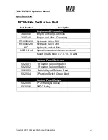
Page 32: ...uel filter Cummins RR00561288 Hydraulic Valve D03 RR00561284 Hydraulic Valve D03 KIO Hydraulic tank oil filter QSB5 9 44 Operation and maintenance manual Fuses blade type 5 7 5 10 20 amp Control Panel Switches 582 001 3 Position Selector Switch 582 002 2 Position Selector Switch 582 003 Switch Keyed Selector Start 582 004 3 Position Switch Green Light Control Panel Relays 582 005 4PDT Relay Socket...

Page 33: ...TEMPEST MVU Operation Manual Copyright 2005 Tempest Technology Corporation 33 ...

Page 34: ...TEMPEST MVU Operation Manual Copyright 2005 Tempest Technology Corporation 34 ...

Page 35: ...TEMPEST MVU Operation Manual Copyright 2005 Tempest Technology Corporation 35 ...

Page 36: ...TEMPEST MVU Operation Manual Copyright 2005 Tempest Technology Corporation 36 ...

Page 37: ...TEMPEST MVU Operation Manual Copyright 2005 Tempest Technology Corporation 37 ...

Page 38: ...TEMPEST MVU Operation Manual Copyright 2005 Tempest Technology Corporation 38 ...

Page 39: ...TEMPEST MVU Operation Manual Copyright 2005 Tempest Technology Corporation 39 ...

Page 40: ...TEMPEST MVU Operation Manual Copyright 2005 Tempest Technology Corporation 40 ...

Page 41: ...TEMPEST MVU Operation Manual Copyright 2005 Tempest Technology Corporation 41 ...

Page 42: ...TEMPEST MVU Operation Manual Copyright 2005 Tempest Technology Corporation 42 ...

Page 43: ...TEMPEST MVU Operation Manual Copyright 2005 Tempest Technology Corporation 43 ...

Reviews: