OPERATION MENU’S
Use messages as mnemonics in your recipe. During the process these messages give an idea
of the progress of the process.
6.2.1.8
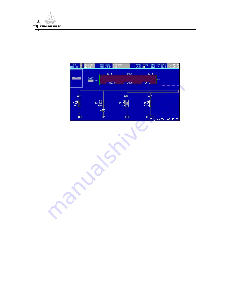
Graphic System Layout
Figure 6-16 Graphic System Layout
There are two options, Graphics-1 and Graphics-2. ‘Graphics–1’ gives the possibility to
design a graphic display. It is used to design the tube type, the pressure valves, the pump
valve, the vacuum valves, the top tube-line valves and the bubbler. It is used in combination
with the screen ‘Graphics–2’. This one is used to draw the other valves and meters used in
the system. Where ‘Graphics–1’ ends, ‘Graphics–2’ will continue.
After the screen has been activated (ON), up to four graphics can be designed and seen.
May be not all elements are present on your system. If this happens, unwanted elements can
be omitted.
T
OUCHSCREEN
R
EFERENCE MANUAL
6-14


