background image

F97CMN and G97CMN: Installation, Start-up, Operating and Service and Maintenance Instructions

Manufacturer reserves the right to change, at any time, specifications and designs without notice and without obligations.

58

SERVICE AND MAINTENANCE PROCEDURES

Untrained personnel  can perform basic maintenance  functions such as

cleaning and replacing air filters. All other operations must be performed

by trained service personnel. A qualified service person should inspect

the furnace once a year.

General

These instructions are written as if the furnace is installed in an upflow

application.  An  upflow  furnace  application  is  where  the  blower  is

located below the combustion and controls section of the furnace, and

conditioned air is discharged upward. Since this furnace can be installed

in  any  of  the  4  positions  shown  in 

Fig. 2

,  you  must  revise  your

orientation to component location accordingly. 

Electrical Controls and Wiring 

The  electrical  ground  and  polarity  for  115-v  wiring  must  be  properly

maintained. Refer to 

Fig. 31

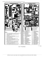
 for field wiring information and to 

Fig. 64

for furnace wiring information. 

NOTE: 

If the polarity is not correct, the STATUS LED on the control

will  flash  code  10  and  prevent  the  furnace  from  heating. The  control

system also requires an earth ground for proper operation of the control

and flame-sensing electrode. 
The 24-v circuit contains an automotive-type, 3-amp. fuse located on the

control, see


Fig. 36

. Any shorts of the 24-v wiring during installation,

service, or maintenance will cause this fuse to blow. If fuse replacement

is required, use ONLY a 3-amp. fuse. The control LED will be off  when

fuse needs to be replaced. 

Troubleshooting 

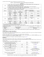
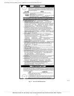
Refer to the service label, see 

Fig. 58

.

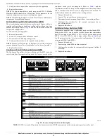
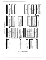
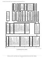
The  Troubleshooting  Guide  can  be  a  useful  tool  in  isolating  furnace

operation  problems.  Beginning  with  the  word  “Start,”  answer  each

question and follow the appropriate arrow to the next item, see 

Fig. 63

.

The Guide will help to identify the problem or failed component. After

replacing any component, verify correct operation sequence. 
Proper  instrumentation  is  required  to  service  electrical  controls.  The

control  in  this  furnace  is  equipped  with  a  Status  Code  LED

(Light-Emitting  Diode)  to  aid  in  installation,  servicing,  and

troubleshooting. Status codes can be viewed at the indicator in blower

door. The amber furnace control LED is either 

.

heartbeat, off or a code

composed of 1 or 2 digits. The first digit is the number of short flashes,

the second digit is the number of long flashes. 
For  an  explanation  of  status  codes,  refer  to  service  label  located  on

control  door  or 

Fig. 58

,  and  the  troubleshooting  guide  which  can  be

obtained from your distributor. 

Retrieving Stored Fault Codes

The stored status codes will NOT be erased from the control memory,

when 115- or 24-v power is interrupted. The control will store up to the

last 7 Status Codes in order of occurrence.

1. To retrieve status codes, proceed with the following: 

NOTE: 

NO  thermostat  signal  may  be  present  at  control,  and  all

blower-OFF delays must be completed.

a. Leave 115-v power to furnace turned on.

b. Look into blower door indicator for current LED status. 

c.  Remove blower door.

NOTE: 

The Status Codes cannot be retrieved by disconnecting the limit

switch. To retrieve Status Codes, follow the procedure below.

2. Turn Setup Switch, SW1-1 “ON.”
3. Manually close blower door switch.
4. Control will flash up to 7 Status Codes.
5. The last Status Code, or 8th Code, will be a heartbeat.
6. Turn SW1-1 “OFF.”
7. A  continuously-lit Amber  LED  will  appear  and  indicates  proper

operation.

8. Release  blower  door  switch,  install  blower  door  and  refer  to  the

SERVICE label on the control door for more information.

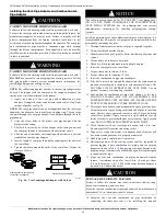
WARNING

!

FIRE, INJURY OR DEATH HAZARD

Failure  to  follow  this  warning  could  result  in  personal  injury,  death

and/or property damage. 

The ability to properly perform maintenance on this equipment requires

certain knowledge, mechanical skills, tools, and equipment. If you do

not  possess  these,  do  not  attempt  to  perform  any  service  and

maintenance  on  this  equipment  other  than  those  procedures

recommended in the Owner’s Manual.

CAUTION

!

ENVIRONMENTAL HAZARD

Failure to follow this caution may result in environmental pollution.
Remove and recycle all components or materials (i.e. oil, refrigerant,

control board, etc.) before unit final disposal.

WARNING

!

ELECTRICAL SHOCK, FIRE OR EXPLOSION HAZARD

Failure to follow this warning could result in personal injury or death,

or property damage. 

Before  installing,  modifying,  or  servicing  system,  main  electrical

disconnect switch must be in the OFF position and install a lockout tag.

There  may  be  more  than  one  disconnect  switch.  Lock  out  and  tag

switch  with  a  suitable  warning  label.  Verify  proper  operation  after

servicing. Always  reinstall access doors after completing service  and

maintenance.

CAUTION

!

ELECTRICAL OPERATION HAZARD

Failure to follow this caution may result in improper furnace operation

or failure of furnace. 
Label all wires prior to disconnection when servicing controls. Wiring

errors can cause improper and dangerous operation. 

WARNING

!

ELECTRICAL SHOCK HAZARD

Failure to follow this warning could result in personal injury or death. 

There may be more  than one electrical  supply to  the  furnace.  Check

accessories and cooling unit for additional electrical supplies that must

be shut off during furnace servicing. Lock out and tag switch with a

suitable warning label. 

Summary of Contents for 0601714

Page 1: ...SERVICE AND MAINTENANCE PROCEDURES 58 Winterization 64 SEQUENCE OF OPERATION 68 PARTS REPLACEMENT INFORMATION GUIDE 74 MODEL NOMENCLATURE 74 A200326 Most states in the USA and jurisdictions in Canada have laws that require the use of Carbon Monoxide CO alarms with fuel burning products Examples of fuel burning products are furnaces boilers space heaters generators water heaters stoves ranges cloth...

Page 2: ...to the exterior of the building at a minimum height of eight 8 feet above grade directly in line with the exhaust vent terminal for the horizontally vented gas fueled heating appliance or equipment The sign shall read in print size no less than one half 1 2 inch in size GAS VENT DIRECTLY BELOW KEEP CLEAR OF ALL OBSTRUCTIONS 4 INSPECTION The state or local gas inspector of the side wall horizontall...

Page 3: ...installation adjustment alteration service maintenance or use can cause carbon monoxide poisoning explosion fire electrical shock or other conditions which may cause personal injury or property damage Consult a qualified service agency local gas supplier or your distributor or branch for information or assistance The qualified service agency must use only factory authorized and listed kits or acce...

Page 4: ... available soap solution made specifically for the detection of leaks to check all connections as specified in the Gas Piping section 6 Always install furnace to operate within the furnace s intended temperature rise range with a duct system which has an external static pressure within the allowable range as specified in the Start Up Adjustments and Safety Check section See furnace rating plate 7 ...

Page 5: ...red faulty installation and or misapplication of the furnace and resulting failure damage or repairs may impact warranty coverage For accessory installation details refer to the applicable instruction literature NOTE Remove all shipping materials loose parts bag and literature before operating the furnace see Table 2 Table 2 Loose Parts Bag A12182 Fig 4 Prohibited Installations NOTICE Important In...

Page 6: ...al Electrical Code NEC NFPA 70 CANADA Current edition of Canadian Electrical Code CSA C22 1 Condensate Drain Connection US Current edition of National Standard Plumbing Code Section 8 7 Canada Current edition of National Plumbing Code of Canada in Canada ELECTROSTATIC DISCHARGE ESD PRECAUTIONS PROCEDURE 1 Disconnect all power to the furnace Multiple disconnects may be required DO NOT TOUCH THE CON...

Page 7: ...ntilation fans designed to operate during the heating season If ventilation fans are present in these areas the combustion air pipe must terminate outdoors as a Direct Vent 2 Pipe system CAUTION PERSONAL INJURYAND OR PROPERTY DAMAGE HAZARD Improper use or installation of this furnace may result in premature furnace component failure Unless otherwise prohibited this gas furnace may be used for heat...

Page 8: ...e sum of the areas of all vent connectors in the space The opening shall commence within 12 in 300 mm of the ceiling Appliances in the space shall have clearances of at least 1 in 25 mm from the sides and back and 6 in 150 mm from the front The opening shall directly communicate with the outdoors or shall communicate through a vertical or horizontal duct to the outdoors or spaces crawl or attic th...

Page 9: ...low position Fig 8 shows the condensate trap and tubing before and after relocation Refer to Fig 8 To begin the trap conversion Refer to Condensate Drain section for information how to install the condensate drain A11306 Fig 7 Upflow Trap Configuration Appearance May Vary A11585A A11585B Fig 8 Downflow Trap Configuration Appearance May Vary OTHER THAN FAN ASSISTED TOTAL 1 000 S BTUH GAS INPUT RATE...

Page 10: ...relief tube from relief port on condensate trap Remove middle and right plug from collector box DO NOT DISCARD Remove relief tube from port on collector box Rotate elbow to desired position and torque clamp on inlet 15 lb in Slide relief tube in stand offs to adjust length Attach condensate trap to collector box with screw Align trap over middle and right hand port on collector box Install plugs i...

Page 11: ... secure the heat tape to the trap and sufficiently cover the trap with heat tape may result in freezing and cracking of the trap causing a leak that results in property damage In applications with potential for freezing the above specified heat tape must also adequately cover wrap the remaining condensate drain line to provide freeze protection Wrap the drain trap and drain line with the heat tape...

Page 12: ...ondensate Drain 1 Remove the 7 8 in knock out from the right side of the casing See Fig 14 for suggested knockout removal technique 2 Remove the pre formed rubber drain elbow and two spring clamps from the loose parts bag 3 Slide a spring clamp 1 in 25 mm down the plain end the end without the formed grommet of the drain elbow 4 From inside the casing insert the formed grommet end of the elbow thr...

Page 13: ...e by modifying the formed rubber drain elbow as shown in Fig 16 4 Remove the formed grommet from the rubber drain elbow by cutting the elbow along the vertical line located about 1 3 8 in 35 mm away from the formed grommet see Fig 16 DO NOT DISCARD THE FORMED GROMMET OR THE RUBBER ELBOW Both of these pieces will be used A170128 Fig 15 Drain Trap Connection and Routing Appearance may vary Assemble ...

Page 14: ...the drain pipe which may cause kinks in the elbow or grommet 7 The remaining drain line can be constructed from field supplied 1 2 in CPVC or 3 4 in PVC pipe in compliance with local building codes A factory supplied 1 2 in CPVC to 3 4 in PVC adapter is supplied in the loose parts bag for use as required 8 Install the adapter or connect the 1 2 in CPVC pipe by sliding a spring clamp over the open ...

Page 15: ...nlet These furnaces are shipped with bottom closure panel installed in bottom return air opening This panel MUST be in place when only side return air is used Where required by code seal bottom closure to furnace with tape mastic or other durable sealing method NOTE Side return air openings can be used in UPFLOW and some HORIZONTAL configurations Do not use side return air openings in DOWNFLOW con...

Page 16: ...property damage Local codes may require a drain pan under entire furnace and condensate trap when a condensing furnace is used in an attic application or over a finished ceiling FURNACE CASING WIDTH IN mm APPLICATION PLENUM OPENING FLOOR OPENING A B C D 17 1 2 445 Upflow Applications on Combustible or Noncombustible Flooring subbase not required 16 406 21 5 8 549 16 5 8 422 22 1 4 565 Downflow App...

Page 17: ...ng method Filter Arrangement Filter and Return Duct Sizing Pressure drop must be taken into account when sizing filters filter racks IAQ devices and associated system ductwork See Table 6 for a comparison of Pressure Drop initial clean resistance to airflow versus Airflow for a variety of filter media types and sizes These are representative numbers Consult the filter or IAQ device manufacturers s...

Page 18: ... a variety of filter media types 14 x 25 Filter Factory Accy Washable Representative After Market Filter Media Representative estimates from filter manufacturer data sheets Fiberglass Pleated CFM L s 1 in 2 5 cm 1 in 2 5 cm 2 in 5 cm 1 in 2 5 cm 2 in 5 cm 600 283 0 04 12 0 07 17 0 10 26 0 24 60 0 16 40 800 378 0 06 15 0 10 25 0 15 39 0 34 85 0 23 59 1000 472 0 07 18 0 13 34 0 21 52 0 32 81 1200 56...

Page 19: ...djust outside nut to provide desired height and tighten inside nut to secure arrangement 5 Reinstall bottom closure panel if removed A89014 Fig 27 Leveling Legs Location Relative to Cooling Equipment The cooling coil must be installed parallel with or on the downstream side of the unit to avoid condensation in the heat exchangers When installed parallel with the furnace dampers or other flow contr...

Page 20: ...he most common causes of airflow and or noise complaints in HVAC systems Ductwork Acoustical Treatment NOTE Metal duct systems that do not have a 90 degree elbow and 10 ft 3 M of main duct to the first branch take off may require internal acoustical lining As an alternative fibrous ductwork may be used if constructed and installed in accordance with the latest edition of SMACNA construction standa...

Page 21: ...855 Heating SW1 Maximum Heat Airflow3 1080 1085 1095 1090 1095 1085 1070 1055 1045 1030 Intermediate Heat Airflow3 685 725 730 725 730 See note 4 Minimum Heat Airflow3 560 555 555 550 565 See note 4 Unit Size 0801714 Clg CF Switch settings External Static Pressure ESP Clg Switches SW2 3 SW2 2 SW2 1 0 1 0 2 0 3 0 4 0 5 0 6 0 7 0 8 0 9 1 0 Clg Default OFF OFF OFF 1055 1065 1080 1075 1065 1050 1045 1...

Page 22: ...385 Heating SW1 Maximum Heat Airflow3 1340 1355 1370 1385 1380 1385 1400 1400 1385 1380 Intermediate Heat Airflow3 780 810 835 840 845 See note 4 Minimum Heat Airflow3 595 595 600 595 605 See note 4 Unit Size 1002122 Clg CF Switch settings External Static Pressure ESP Clg Switches SW2 3 SW2 2 SW2 1 0 1 0 2 0 3 0 4 0 5 0 6 0 7 0 8 0 9 1 0 Clg Default OFF OFF OFF 1820 1825 1840 1845 1840 1835 1825 1...

Page 23: ...5 1860 1855 1850 1830 1805 1775 1750 1730 ON ON ON 2200 2200 2200 2190 2185 2170 2145 2085 1990 1890 Maximum Clg Airflow2 2200 2200 2200 2190 2185 2170 2145 2085 1990 1890 CF Switches SW3 3 SW3 2 SW3 1 Cont Fan Default OFF OFF OFF 930 925 915 900 885 See note 4 Continuous Fan Airflow SW3 OFF OFF ON 765 745 740 705 680 See note 4 OFF ON OFF 930 925 915 900 885 See note 4 OFF ON ON 1095 1100 1110 11...

Page 24: ...s codes before the furnace has been connected Refer to current edition of NSCNGPIC in Canada After all connections have been made purge lines and check for leakage at furnace prior to operating furnace PRESSURE TESTING ABOVE psig The furnace and it s individual shut off valve must be disconnected from the gas supply piping system during any pressure testing of that system at test pressures in exce...

Page 25: ... must be located within sight of the furnace Verify that the voltage frequency and phase correspond to that specified on unit rating plate Also check to be sure that service provided by utility is sufficient to handle load imposed by this equipment Refer to rating plate or Table 9 for equipment electrical specifications U S A Installations Make all electrical connections in accordance with the cur...

Page 26: ...through the furnace top panel is used a 7 8 in 22 mm hole must be drilled through the top panel 2 Drill two 2 1 8 in 3 mm pilot holes through the dimples in the furnace casing near the 7 8 in knock out A12226 Fig 33 Installing J Box When Used Appearance May Vary WARNING ELECTRICAL SHOCK AND FIRE HAZARD Failure to follow this warning could result in personal injury death or property damage The cabi...

Page 27: ...shing into the furnace casing 7 Install the green ground screw to the J Box bracket and attach both ground wires to the green ground screw 8 Connect any code required external disconnect s to field power wiring 9 Connect field power and neutral leads to furnace power leads inside the external electrical box as shown in Fig 34 Power Cord Installation in Furnace J Box NOTE Power cords must be able t...

Page 28: ...aintenance could cause this fuse to blow If fuse replacement is required use ONLY a 3 amp fuse of identical size see Fig 36 Thermostats For best results use a communicating wall control to control this modulating furnace A single stage or two stage heating and cooling thermostat can be used with the furnace The furnace control board CPU will control the furnace and outdoor unit staging A two stage...

Page 29: ...required orientation Venting for this furnace shall follow all Local codes for Category IV venting systems This furnace is CSA approved for venting with PVC ABS DWV venting systems This furnace is also CSA approved for venting with M G DuraVentRPolyProR or Centrotherm InnoflueR polypropylene venting systems straight pipe and fittings elbows reducers increasers connectors adapters only NOTE THESE I...

Page 30: ...ustion air and vent pipes and be terminated individually as shown in Fig 38 for Direct Vent 2 Pipe system or Fig 39 for ventilated combustion air option A furnace shall not be connected to a chimney flue serving a separate appliance designed to burn solid fuel Other gas appliances with their own venting system may also use the abandoned chimney as a raceway providing it is permitted by local code ...

Page 31: ...ing polypropylene venting systems all venting materials used including the vent terminations must be from the same manufacturer Venting Systems A13305 Fig 38 Combustion Air and Vent Pipe Termination for Direct Vent 2 Pipe System WARNING CARBON MONOXIDE POISONING HAZARD Failure to follow the instructions outlined below for each appliance being placed into operation could result in carbon monoxide p...

Page 32: ...orities All air for combustion is piped directly to the furnace from a space that is well ventilated with outdoor air such as an attic or crawl space and the space is well isolated from the living space or garage Combustion air requirements for this option are the same as the requirements for providing outside air for combustion for a single pipe vent system Refer to the Air For Combustion and Ven...

Page 33: ...s Termination should be positioned so that it will not be affected by sustained prevailing winds over 30 mph wind eddy such as inside building corners or by recirculation of flue gases airborne leaves or light snow 4 Termination or termination kit should be positioned where it will not be damaged by or subjected to foreign objects such as stones balls etc 5 Termination or termination kit should be...

Page 34: ...ments in these instructions are adhered to Refer to the appropriate Vent Termination section above for locating the vent termination The concentric vent kit currently cannot be modified to attach an elbow to the vent portion of the rain cap A tee attached to the rain cap could potentially direct the flue gas plume toward the intake air stream and contaminate the incoming combustion air for the fur...

Page 35: ...BTUh 15 kW 12 in 305 mm for appliances 50 000 BTUh 15kW K Clearance to a mechanical air supply inlet 6 ft 1 8 M 3ft 9 M above if within 10 ft 3 M horizontally L Clearance under a veranda porch deck or balcony 12 in 305 mm Permitted only if veranda porch deck or balcony is fully open on a minimum of two sides beneath the floor See Note 4 Manufacturer s Recommendation See Notes 3 8 M Clearance to ea...

Page 36: ...or to the side of the opening 1 ft 3M above the opening Manufacturer s Recommendation See Note 8 K Clearance to a mechanical air supply inlet 6 ft 1 8 M 3ft 9 M above if within 10 ft 3 M horizontally L Clearance under a veranda porch deck or balcony 12 in 305 mm Permitted only if veranda porch deck or balcony is fully open on a minimum of two sides beneath the floor See Note 4 Manufacturer s Recom...

Page 37: ...arance Table for all two pipe terminations or Non Direct Vent Clearance Table for all single pipe terminations For clearance distances when vent termination is located more than 6 ft 2 M away from an inside corner refer to the appropriate Direct Vent or Non Direct Vent Clearance Table Clearance description when termination is at least 3 ft 1 M away and not more than 6 ft 2 M away from an inside co...

Page 38: ...Air Inlet Moisture Trap To prevent moisture from trickling into the furnace vestibule a trap can be installed in the intake air pipe near the furnace To prevent moisture 3 76 mm 12 305 mm Pipe hangar Ventilated Combustion Air intake termination in crawl space Ventilated Combustion Air intake pipe CRAWL SPACE ATTIC highest level of insulation FURNACE PIPE DIAMETER TRANSITION IN VERTICAL SECTION NOT...

Page 39: ...e is used on the termination Alberta and Saskatchewan when required record the equivalent length of the Tee used 5 Calculate Total Equivalent Vent Length by adding the equivalent lengths of the fittings to the lengths of the individual vent and combustion air pipes 6 When using polypropylene venting systems with flexible vent pipes perform adjustments for the equivalent length of the flexible vent...

Page 40: ...ed spaces cannot exceed total allowable pipe length as calculated from Table 11 A170122A Fig 49 Recommended Combustion Air Inlet Moisture Trap NOTE Maximum Equivalent Vent Length MEVL includes standard and concentric vent termination and does NOT include elbows Use Table 11 Deductions from Maximum Equivalent Vent Length to determine allowable vent length for each application Table 11 Maximum Equiv...

Page 41: ...ets the casing Fold the knockout down with duct pliers and work the knockout back and forth until it is removed Trim any excess metal from the knockout with tin snips Maximum Equivalent Vent Length Meters Meters Unit Size 60 000 80 000 100 000 120 000 Altitude meters Pipe Dia mm 38 51 64 76 38 51 64 76 102 51 64 76 102 64 76 102 0 610 15 2 30 4 53 3 60 9 9 1 28 9 39 6 53 3 60 9 13 7 24 3 53 3 60 9...

Page 42: ...e the clamp to 15 lb in see Fig 50 Fig 55 A14546 Fig 50 Near Furnace Vent Connections A170006 Fig 51 Inducer Vent Elbow Appearance May Vary UPFLOW LEFT CONFIGURATION A11309A UPFLOW RIGHT CONFIGURATION A11308A UPFLOW VERTICAL VENT A11310A Fig 52 Upflow Configurations Appearance may vary See Notes for Venting Options DOWNFLOW LEFT CONFIGURATION A11311A DOWNFLOW RIGHT CONFIGURATION A11312A DOWNFLOW V...

Page 43: ...N A11337 HORIZONTAL RIGHT LEFT VENT CONFIGURATION A11336 HORIZONTAL RIGHT RIGHT VENT CONFIGURATION A11335 Fig 55 Horizontal Right Appearance may vary See Notes for Venting Options NOTES FOR VENTING OPTIONS 1 Attach vent pipe adapter with gasket to furnace casing 2 Align notches in rubber coupling over standoffs on adapter Slide clamps over the coupling 3 Slide vent pipe through adapter and couplin...

Page 44: ...3 4 2 3 4 20 10 50 40 10 75 95 10 75 105 5 55 50 5 65 105 5 65 125 0 10 20 15 10 55 45 10 65 50 5 25 15 5 65 50 5 65 60 20 10 10 10 35 25 10 45 30 5 10 5 5 45 30 5 50 40 40 10 5 10 25 15 10 30 20 5 5 5 30 20 5 35 25 Winter Design Temp C Unit Size 40 000 BTUH 60 000 BTUH Uninsulated 3 8 in Insulation 1 2 in Insulation Uninsulated 3 8 in Insulation 1 2 in Insulation Pipe Dia mm 38 51 64 38 51 64 38 ...

Page 45: ...generous layer of cement primer to pipe fitting socket and end of pipe to insertion mark Quickly apply approved cement to end of pipe and fitting socket over primer Apply cement in a light uniform coat on inside of socket to prevent buildup of excess cement Apply second coat DO NOT CEMENT POLYPROPYLENE FITTINGS 13 While cement is still wet twist pipe into socket with 1 4 in turn Be sure pipe is fu...

Page 46: ...g for a 3 inch 80 mm ND concentric vent kit For two pipe or single pipe vent systems a flashing for each pipe of the required diameter will be necessary It is recommended that the flashing be installed by a roofer or competent professional prior to installing the concentric vent The terminations can be installed on a flat or pitched roof Concentric Vent Single or multiple concentric vent must be i...

Page 47: ... using same procedures as used for system piping DO NOT CEMENT POLYPROPYLENE FITTINGS 2 Pipe Direct Vent and 1 Pipe Ventilated Combustion Air Vent Termination NOTE Follow the instructions of the vent terminal manufacturer These instructions are provided as a reference only Determine an appropriate location for termination kit using the guidelines provided in section Locating The Vent Termination i...

Page 48: ...l Description Type ASTM ULC UL Specification Pipe Fittings Solvents Primers Cements PVC Pressure Pipe Schedule 40 D1785 UL 1738 DWV Schedule 40 D1785 D2665 D2466 Cellular Core Schedule 40 F891 or F656 D2564 SDR 26 N A D2241 D2665 SDR 21 N A D2241 IPEX Schedule 40 ULC S636 ULC S636 ULC S636 ULC S636 Royal Pipe Schedule 40 ULC S636 ULC S636 ULC S636 ULC S636 ABS ABS Schedule 40 D1527 D2468 Clear Cle...

Page 49: ...nd the Adjustments section for setup switch configurations To set these setup switches for the appropriate requirement 1 Remove blower door 2 Locate setup switches on furnace control Measure the required linear length of RIGID air inlet and vent pipe insert the longest of the two here 100 ft Of rigid pipe 20 ft Of flexible pipe 80 ft 24 M Use length of the longer of the vent or air inlet piping sy...

Page 50: ...r door Continuous Fan CF Setup Switches SW3 The Continuous Fan airflow selection via Setup switches SW3 is also the switch setting for low speed cooling when the furnace is used with a two speed cooling or heat pump unit Refer to Table 5 and the Adjustments section for setup switch configurations This setup feature allows continuous fan airflow or low cooling airflow to be adjusted To set desired ...

Page 51: ...rnings could result in personal injury or death Failure to use a properly configured trap or NOT water priming trap before operating furnace may allow positive pressure vent gases to enter the structure through drain tube Vent gases contain carbon monoxide which is tasteless and odorless CAUTION UNIT OPERATION HAZARD Failure to follow this caution may result in intermittent unit operation or perfo...

Page 52: ...sure must be checked with the furnace operating in maximum heat This is necessary to make sure the inlet gas pressure does not fall below the minimum pressure of 4 5 in w c for natural gas The maximum inlet gas pressure is 13 6 in of water column If the inlet pressure is too low you will not be able to adjust the manifold pressure to obtain the proper input rate To check the inlet gas pressure 1 M...

Page 53: ...lve without Tower Pressure Ports 10 Main burner flame should be clear blue almost transparent 11 After adjusting the Maximum Heat manifold pressure remove jumpers across thermostat connections to terminate the call for heat 12 Wait for blower off delay to finish then reset 115 v power to furnace Adjust Manifold Pressure Minimum Heat To adjust manifold pressure to obtain input rate for Minimum Heat...

Page 54: ...will result in incorrect temperature measurements due to possible changes in duct static pressure and airflow When setup switch SW1 4 is ON operation will be near the high end of the rise range for improved comfort Furnace must operate within ranges of temperature rise specified on the furnace rating plate Determine air temperature rise as follows WARNING FIRE HAZARD Failure to follow this warning...

Page 55: ... and the blower to turn on 4 Allow the supply temperature to stabilize and verify the proper rise range If the temperature rise is too high or too low in Intermediate Heat 1 Remove jumpers from R and W W1 2 Wait until the blower off delay is completed 3 Turn 115 VAC power off 4 Check the position of setup switch SW1 3 When set to ON airflow is raised 18 for Minimum Heat and for Intermediate Heat F...

Page 56: ...as shown in Fig 64 across the R and W subbase terminals or R and W wires at wall d Record amp draw across terminals when furnace is in minimum heat and after blower starts e Set heat anticipator on thermostat per thermostat instructions and install on subbase or wall f Turn SW1 2 switch OFF g Install blower door h Electronic thermostat Set cycle rate for 3 cycles per hr Check Safety Controls The f...

Page 57: ... 60 42 3 2 0 50 42 3 3 0 55 42 3 4 0 55 650 43 3 5 0 55 43 3 6 0 55 43 3 7 0 60 43 3 8 0 60 675 44 3 7 0 60 44 3 8 0 60 43 3 4 0 55 43 3 5 0 55 10000 700 44 3 4 0 55 44 3 5 0 55 44 3 7 0 60 44 3 8 0 60 3048 725 44 3 2 0 50 44 3 3 0 55 44 3 4 0 55 44 3 5 0 55 Orifice numbers shown in BOLD are factory installed U S A Only to U S A Only to U S A Only to MODULATING FURNACE S A G L A R U T A N F O Y T ...

Page 58: ...the troubleshooting guide which can be obtained from your distributor Retrieving Stored Fault Codes The stored status codes will NOT be erased from the control memory when 115 or 24 v power is interrupted The control will store up to the last 7 Status Codes in order of occurrence 1 To retrieve status codes proceed with the following NOTE NO thermostat signal may be present at control and all blowe...

Page 59: ...age sagging pipes or broken fittings Have vent pipes vent system serviced by a qualified service agency 6 Inspect any accessories attached to the furnace such as a humidifier or electronic air cleaner Perform any service or maintenance to the accessories as recommended in the accessory instructions Cleaning and or Replacing Air Filter The air filter type may vary depending on the application or or...

Page 60: ...aft NOTE Mark blower mounting arms and blower housing so each arm is positioned at the same hole location during reassembly c Mark blower wheel orientation and cutoff plate location to ensure proper reassembly d Remove screws securing cutoff plate and remove cutoff plate from housing e Remove bolts holding motor mounts to blower housing and slide motor and mounts out of housing f Remove blower whe...

Page 61: ...rop it up with a small piece of wood or folded cardboard 13 Support the burner assembly and remove the screws that attach the burner assembly to the heat exchanger cell panel 14 Remove wires from both rollout switches 15 Slide one piece burner out of slots on sides of burner assembly 16 Remove the flame sensor from the burner assembly 17 Optional Remove the Hot Surface Igniter HSI and bracket from...

Page 62: ...se items 5a through 5d 7 Reconnect igniter harness to the igniter dressing the igniter wires to ensure there is no tension on the igniter itself see Fig 66 8 Turn on gas and electrical supplies to furnace 9 Verify igniter operation by initiating control board self test feature or by cycling thermostat 10 Replace control door Flushing Collector Box and Drainage System 1 Turn off gas and electrical ...

Page 63: ...tual heating of the tape Check the following 1 Check for signs of physical damage to heat tape such as nicks cuts abrasions gnawing by animals etc 2 Check for discolored heat tape insulation If any damage or discolored insulation is evident replace heat tape 3 Check that heat tape power supply circuit is on Cleaning Heat Exchangers The following items must be performed by a qualified service techn...

Page 64: ...9 Remove the middle unused rubber plug from the port on the collector box opposite the condensate trap see Fig 59 10 Repeat Steps 5 through 8 11 If a condensate pump is used check with pump manufacturer to verify pump is safe for use with antifreeze used Allow pump to start and pump anti freeze to open drain 12 Replace main door 13 When furnace is re started flush condensate pump with clear water ...

Page 65: ...ltaneously until the heartbeat flashes When done put setup switch SW1 1 in the OFF position Was there a previous status code other than the heartbeat Go to section below for the status code that was flashed Does the control respond to W W1 W2 Y1 Y Y2 and G 24V thermostat signals Run system through a minimum heat maximum heat or cooling cycle to check operation Status codes are erased after 72 hour...

Page 66: ...nal and burners will not stay on repeat check in maximum heat If burners will still not stay on replace control If burners operate in maximum heat then switch to intermediate heat check manifold pressure If OK check burner carryover and flame sensor location Clean flame sensor with fine steel wool and recheck current Nominal current is 4 0 to 6 0 microamps Is current near typical value Replace ele...

Page 67: ...will briefly go high several times a second If you have a digital voltmeter with a bar graph it will show a large change in magnitude on the bar graph several times a second If you have a standard digital voltmeter it will show a brief fluctuation in voltage and the magnitude may vary depending on the voltmeter used Does the voltage fluctuate as described in the previous step Connect a DC voltmete...

Page 68: ...elect intermediate heat for 45 seconds minimum heat for 19 minutes and then switch to maximum heat as long as the thermostat continues to call for heat The furnace control CPU then uses this information to calculate the modulating rate the furnace will operate at on the next heating cycle If the calculated modulating rate is between 40 99 then the furnace control CPU will operate for 45 seconds at...

Page 69: ... W circuit is opened de energizing the gas valve GV pin 5 stopping gas flow to the burners and humidifier terminal HUM The inducer motor IDM will remain energized for a 15 second post purge period The blower motor BLWM and air cleaner terminal EAC 1 will remain energized at minimum heat airflow or transition to minimum heat airflow for 90 120 150 or 180 seconds depending on selection at blower OFF...

Page 70: ...e the cooling off delay to 5 seconds see Fig 58 3 Dehumidification Mode See Fig 36 for thermostat connections The dehumidification output D or DHUM on the Thermostat should be connected to the furnace control thermostat terminal DHUM When there is a dehumidify demand the DHUM input is activated which means 24 vac signal is removed from the DHUM input terminal In other words the DHUM input logic is...

Page 71: ...ng the blower airflow If Y Y2 input is still energized the furnace control CPU will transition the blower motor BLWM airflow to cooling airflow If Y Y2 input signal disappears and the Y1 input is still energized the furnace control CPU will transition the blower motor BLWM to low cooling airflow If both the Y1 and Y Y2 signals disappear at the same time the blower motor BLWM will remain on at mini...

Page 72: ...tion Start up Operating and Service and Maintenance Instructions Manufacturer reserves the right to change at any time specifications and designs without notice and without obligations 72 A200363 Fig 71 Service Label Information ...

Page 73: ...n Start up Operating and Service and Maintenance Instructions Manufacturer reserves the right to change at any time specifications and designs without notice and without obligations 73 338307 201 Rev N A200364 Fig 72 Wiring Diagram ...

Page 74: ... box Condensate trap Condensate trap elbow Gaskets Inducer Inducer assembly Inducer motor capacitor when used Inducer motor module when used Pressure switch es TO OBTAIN INFORMATION ON PARTS Consult your installing dealer or a licensed Heating and Air Conditioning company of your choice INTERNATIONAL COMFORT PRODUCTS a division of Carrier Corporation LEWISBURG TN 37091 U S A Have available the mod...

Reviews: