F97CMN and G97CMN: Installation, Start-up, Operating and Service and Maintenance Instructions
Manufacturer reserves the right to change, at any time, specifications and designs without notice and without obligations.
68
SEQUENCE OF OPERATION
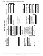
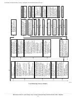
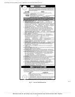
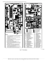
Using the schematic diagram, follow the sequence of operation through
the different modes, see
. Read and follow the wiring diagram
very carefully!!
NOTE:
If a power interruption occurs during a call for heat (W/W1 or
W/W1-and-W2), the control will start a 90-second blower-only ON
period two seconds after power is restored, if the thermostat is still
calling for gas heating. The amber LED light will flash code 1+2 during
the 90-second period, after which the LED will flash a heartbeat
(bright-dim), as long as no faults are detected. After the 90-second
period, the furnace will respond to the thermostat normally.
The blower door must be installed for power to be conducted through the
blower door interlock switch ILK to the furnace control CPU,
transformer TRAN, inducer motor IDM, blower motor BLWM, hot
surface igniter HSI, and gas valve GV.
Communicating Control and Modulating Heating
Best comfort will be attained when a communicating wall control is used
with this product. Wiring and set-up instructions are provided with the
communicating control. See the furnace data sheet accessory section for
help in selecting the appropriate communicating control for this furnace.
When a communicating control is used, the furnace will modulate
through its full operation range, or can be limited via the minimum and
maximum CFM configurations.
Operation of the furnace at the beginning and end of each heating cycle
will be the same as detailed below in the Single-Stage Thermostat
section EXCEPT that the communicating control will send modulating
rate command signals through the communication bus rather than
energizing the 24-v thermostat terminals. Note that the R to W/W1
circuit signal will be controlled by the COMMR relay on the furnace
control. See the wiring diagram in
Single-Stage Thermostat and Modulating Heating
(Adaptive Mode)
See
for thermostat connections
.
NOTE:
Minimum-heat only switch SW1-2 selects the minimum-heat
only operation mode when ON. Intermediate-heat only switch SW4-2
selects intermediate-heat only operation mode when ON. If both
switches are ON the furnace control will default to intermediate-heat. If
either or both switches are ON, the furnace control will operate at
two-stages only as referenced in Two Stage Thermostat section below. If
both switches are OFF the furnace control will operate in the adaptive
heating mode in response to a call for heat, see
. When the W2
thermostat terminal is energized it will always cause maximum-heat
operation as long as the R to W circuit is closed, regardless of the setting
of the minimum-heat or intermediate-heat only switches.
This furnace can operate as a modulating furnace with a single-stage
thermostat because the furnace control CPU includes a programmed
adaptive sequence of controlled operation, which selects a modulated
rate between minimum- and maximum-heat
.
This selection is based
upon the stored history of the length of previous gas-heating periods of
the single-stage thermostat.
The furnace will start up in either intermediate-, or maximum-heat. The
furnace will transition and operate at minimum-heat or the calculated
modulating rate after starting and operating for 45 seconds at
intermediate-heat. The furnace control CPU defaults to minimum-heat
on the first thermostat cycle and calculates the modulating rate that the
furnace should run at for 19 minutes on subsequent heat cycles.
If the power is interrupted, the stored modulating rate is erased and the
furnace control will select intermediate-heat for 45 seconds,
minimum-heat for 19 minutes and then switch to maximum-heat, as long
as the thermostat continues to call for heat. The furnace control CPU
then uses this information to calculate the modulating rate the furnace
will operate at on the next heating cycle. If the calculated modulating
rate is between 40% - 99% then the furnace control CPU will operate for
45 seconds at intermediate-heat, and then operate at the calculated
modulating rate for up to 19 minutes and then switch to maximum-heat
as long as the thermostat continues to call for heat. If the calculated
modulating rate is 100% then the furnace control will only operate at
maximum-heat until the thermostat is satisfied.
The wall thermostat ”calls for heat”, closing the R to W circuit. The
furnace control CPU performs a self-check, verifies the low, medium,
and high pressure switch contacts LPS, MPS, and HPS are open, then
de-energizes the PSR relay to close the NC contact.
1.
Inducer Prepurge Period
-
The furnace control CPU turns on
inducer motor IDM and slowly increases the inducer motor speed.
After the low pressure switch LPS closes the furnace control CPU
continues to increase the inducer motor speed until the medium
pressure switch MPS closes. When the medium pressure switch
MPS closes, inducer motor RPM is noted by the furnace control
CPU, and a 25-second prepurge period begins. The RPM is used to
evaluate vent system resistance. This evaluation is then used to
determine the required RPM necessary to operate the inducer motor
during pre-purge, the first 45 seconds of intermediate-heat, or any
modulating rate that the furnace will transition to after the blower
on-delay is completed.
NOTE:
The heat cycle can start in either intermediate- or
maximum-heat. If a maximum-heat cycle is initiated, the furnace control
CPU will continue to increase the inducer motor speed after the medium
pressure switch MPS closes. When the medium pressure switch closes,
inducer motor RPM is noted by the furnace control CPU, and a
25-second prepurge period begins. The RPM is used to evaluate vent
system restriction. This evaluation is then used to determine the required
RPM necessary to operate the inducer motor in maximum-heat
pre-purge, or maximum-heat. The high pressure switch HPS should be
closed before ignition but the furnace control ignores this input until
after ignition occurs.
2.
Igniter Warm-Up
- At the end of the prepurge period, the
Hot-Surface Igniter HSI is energized for a 17-second igniter
warm-up period
3.
Trial-For-Ignition Sequence
-
When the igniter warm-up period is
completed the main gas valve relay contact GVR closes to energize
the gas valve solenoid GV (pin 5). The gas valve solenoid GV (pin
5) permits gas flow to the burners where it is ignited. Five seconds
after the GVR closes, a 2-second Flame-Proving period begins. The
HSI igniter will remain energized until flame is sensed or until the
2-second flame proving period begins.
4.
Flame-Proving
- When the burner flame is proved at the
flame-proving sensor electrode FSE, the furnace control CPU
begins the blower-ON delay period and continues to hold the gas
valve GV (pin 5) open. If the burner flame is not proved within two
seconds, the furnace control CPU will close the gas valve GV (pin
5), and the furnace control CPU will repeat the ignition sequence
for up to three more Trials-For-Ignition before going to
Ignition-Lockout.
Lockout will be reset
automatically after three
hours, or by momentarily interrupting 115 vac power to the furnace,
or by interrupting 24 vac power at SEC1 or SEC2 to the furnace
control CPU (not at W/W1, G, R, etc.).
If flame is proved when flame should not be present, the furnace
CAUTION
!
UNIT OPERATION HAZARD
Failure to follow this caution may result in intermittent unit operation.
Furnace control must be grounded for proper operation or control will
lock out. Control is grounded through green/yellow wire routed to gas
valve and burner box screw.

