INSTALLATION INSTRUCTIONS
Gas Furnace: (F/G)MAC
440 01 4201 01
17
Specifications subject to change without notice.
12. If the “Z” pipe does not extend through the casing, slide a
piece of field supplied CPVC through the grommet in the
casing, otherwise, go to Step 17.
13. Cement a 1/2-in. CPVC coupling to the end of the CPVC
pipe.
14. Apply cement to the end of the “Z” pipe connected to the
condensate trap.
15. Connect the field-supplied CPVC pipe to the CPVC pipe
connected to the condensate trap.
16. Cut off excess CPVC pipe outside the casing.
17. Connect additional 1/2-in. CPVC piping to a condensate
pump approved for use with acidic furnace condensate
or to a code-approved drain.
18. When a condensate pump is not used, slope the pipe
away from the furnace to allow for proper drainage.
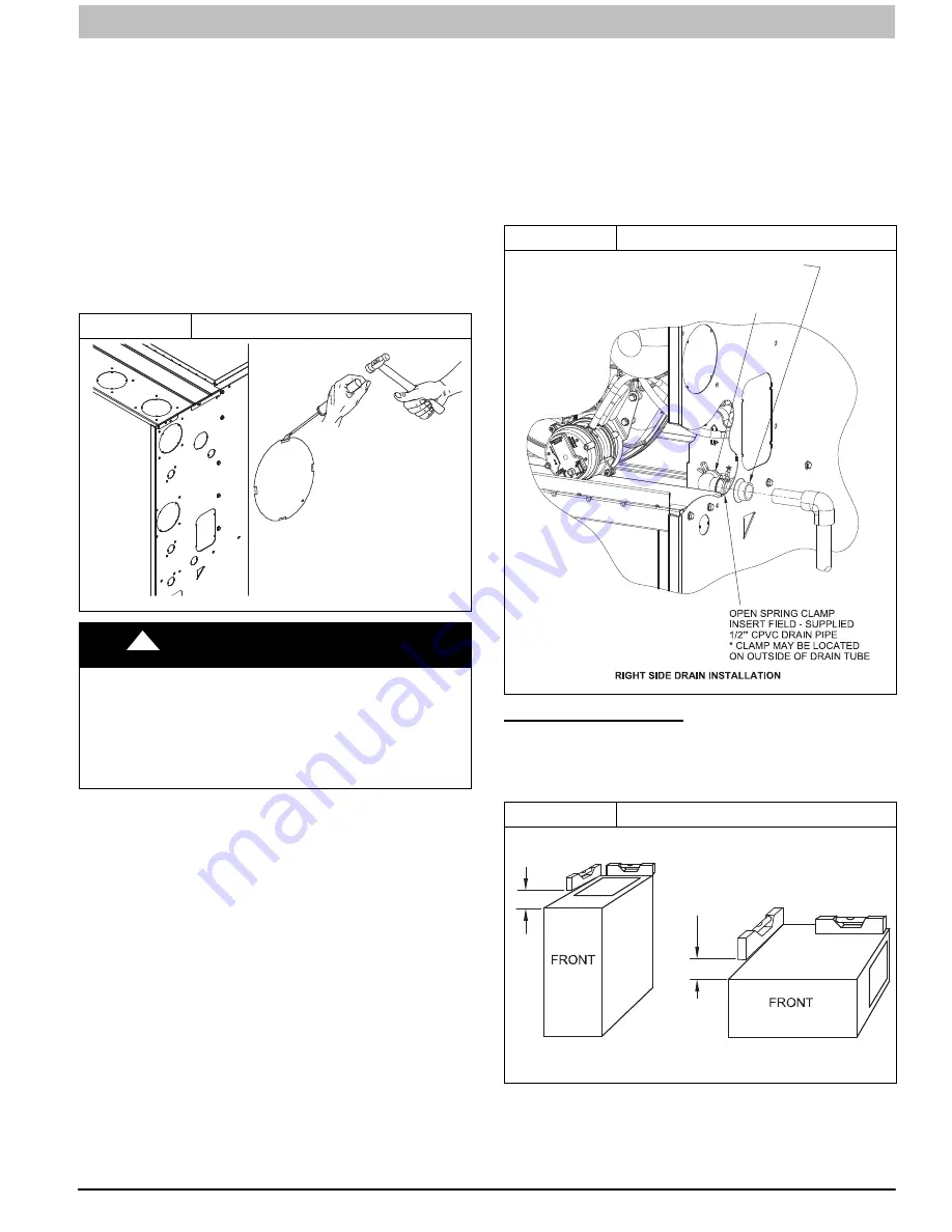
Figure 15
Knockout Removal
A11305
!
CAUTION
CUT HAZARD
Failure to follow this caution may result in personal injury.
Sheet metal parts may have sharp edges or burrs. Use
care and wear appropriate protective clothing, safety
glasses and gloves when handling parts, and servicing
furnaces.
Horizontal Orientation
1. In the Horizontal orientation, a field supplied accessory
drain trap grommet is required to seal the gap between
the casing and the condensate trap for direct vent
applications only. The condensate trap outlet extends 2
inches (51 mm) below the furnace casing. To allow for
servicing the trap, the condensate drain tube in the loose
parts bag can be modified to make a coupler to allow for
future service of the condensate trap and drain line.
2. Remove the knock-out for the condensate trap in the
side of the casing.
3. Install the drain trap grommet in the casing (for direct
vent applications). If necessary, remove the trap, install
the grommet and re-install the trap.
4. Remove the pre-formed drain tube, the offset 1/2-in.
CPVC pipe and two spring clamps from the loose parts
bag.
5. Remove the formed grommet on the tube to create an
elbow or straight connector. (See
Figure 16
)
6. Connect the cut tube to the outlet of the condensate trap
with 1 spring clamp.
7. Slide the other spring clamp down the plain end of the
drain tube.
8. Connect additional 1/2
−
in. CPVC piping to the open end
of the tube.
9. Slide the spring clamp down over the 1/2
−
in. CPVC pipe.
10. Connect additional 1/2
−
in. CPVC piping to a condensate
pump approved for use with acidic furnace condensate
or to a code
−
approved drain.
11. When a condensate pump is not used, slope the pipe
away from the furnace to allow for proper drainage.
Figure 16
Formed Tube Grommet
INSTALL CLAMPS ON DRAIN TUBE
ATTACH DRAIN TUBE TO CONDENSATE
DRAIN TRAP
PULL DRAIN STUB
THROUGH CASING
A11342
INSTALLATION
UPFLOW INSTALLATION
NOTE
: The furnace must be pitched forward as shown in
Figure 17
for proper condensate drainage.
Figure 17
Furnace Pitch Requirements
LEVEL 0-IN. (0 MM) TO
1/2-IN. (13 MM) MAX
UPFLOW OR
DOWNFLOW
HORIZONTAL
MIN 1/4-IN. (6 MM) TO
1/2-IN. (13 MM) MAX
A11237
Supply Air Connections
For a furnace not equipped with a cooling coil, the outlet duct
shall be provided with a removable access panel. This opening
shall be accessible when the furnace is installed and shall be of
such a size that the heat exchanger can be viewed for possible


