3
ELECTRIC HEATER FUNCTION AND
TROUBLESHOOTING
This section describes EHK3 series electric heaters by examining
functional operation of this heater.
Service can be completed with heater in place. Shut off power
before servicing.
DESCRIPTION OF ELECTRIC HEATER COMPONENTS
A. Limit Switch
The limit switch is a temperature sensitive control that’s function is
to prevent system from overheating in abnormal conditions. The
temperature settings often vary from heater to heater due to
variations in airflow patterns and element radiant heat conditions.
The devices are sized to remain on-line under heat pump
conditions (115
_
F air off coil) and minimum CFM, but trip to
prevent outlet air conditions above 200
_
F or excessive component
or duct temperatures. The device itself consists of a bimetallic disc,
which when overheated “snaps through” to open a normally closed
high-voltage, high-current switch. When system temperatures cool
sufficiently, the switch will automatically reset to its closed
position. Normal failure mode for this switch is open.
If a limit switch has been determined to be defective, NEVER
BYPASS THE LIMIT SWITCH. When replacing limit switch,
ensure that it is replaced with a limit switch of identical opening
temperature and closing differential. Limits switches are typically
color
−
coded to identify their range.
B. Relay
The relays used on these heat kits utilize rectifier boards that sit
atop the double pole relays. The rectifier board converts the 24AC
signal into a DC current to drive relay. This heater control system
does not incorporate any time delays. The fan motor is
interconnected to one of the heater elements, this ensures fan
operation during heater operation.
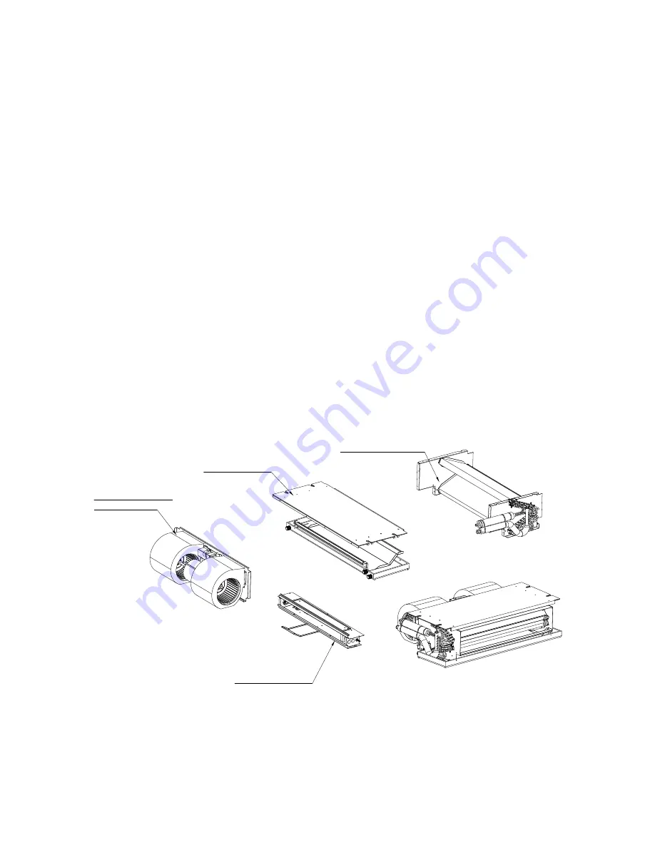
NOTE: This illustration is for reference only. Unit may differ in appearance or may not include all components shown.
BLOWER PARTS
DUCT COMPONENTS
WRAPPER ASSY
EVAPORATOR PARTS
ELECTRICAL PARTS
0.8315
A180050
Fig. 1
−
Expanded Parts


