CF Series Portable Chiller : Air & Water-Cooled : 5 - 40 Tons
Page: 25
TEMPTEK, INC.
525 East Stop 18 Road Greenwood, Indiana 46142
317-887-6352 Fax: 317-881-1277
Email: service@Temptek.com
3.
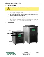
WATER QUALITY CONTROL. Lack of, as well as, improper water treatment can
damage the chilling unit. The services of competent water treatment specialist
should be obtained and their recommendations followed. It is the equipment
owner’s responsibility to prevent damage from foreign material or inadequate
water treatment. See water treatment section in
section 1.6 of this manual for more information.
4.
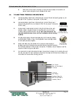
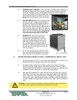
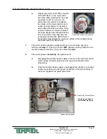
FOR AUTOMATIC FILL: Always install a manual
shut off valve on the make-up water supply on
the outside of the unit. When electrical power is
applied to the unit but the On/Off Selector is in
the ‘off’ position open the owner supplied shut off
valve. The level switch will activate the make-up
solenoid which will open and the water supply will
fill the reservoir tank. Do not use automatic fill
when operating at temperature below 48°F.
5.
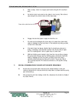
MANUAL FILL: Disconnect and lock out
the electrical power supply and remove
all necessary cover panels to access the
reservoir. Add fluid directly to the reservoir.
When the pump is first started, as process
lines are filled and air is purged, additional
fluid may be required to restore the reservoir to
the correct level. Verify reservoir level via the
coolant sight glass.
6.
Do not use deionized water in this unit unless
your unit was specifically designed for use with
deionized water. Consult factory if not certain.
B.
PROPER ROTATION (PHASING) OF SCROLL COMPRESSORS & PUMPS & FANS
1.
Correct compressor, fan (on air-cooled units) and pump rotation is critical for unit
performance and to avoid severe damage to the compressor.
2.
All portable chiller compressors and pumps will be set to rotate in the same
direction during the testing process at the factory except for units with outdoor
remote condensers. The rotation of compressors and pumps on units with remote
condensers must be checked for correct rotation independently.
3.
After electrical installation the rotation must be checked by observing the pump
motor shaft on the end of the pump and comparing its rotation to the directional
arrow on the motor. If the rotation needs to be changed it should be done at the
main power entry by switching any two power conductors at the terminal block or
customer supplied main power disconnect. Recheck rotation before operating the
units.
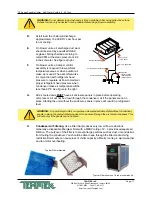
Make-up solenoid valve
Typical coolant sight glass
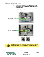
WARNING: The electrical power is engaged at this point and caution must be observed while
the electrical supply is engaged and cabinet panels are removed and opened.
Summary of Contents for CF Series
Page 2: ......
Page 6: ...Page 6 THIS PAGE INTENTIONALLY BLANK ...
Page 22: ...Page 22 THIS PAGE INTENTIONALLY BLANK ...

