background image

Temperature Control Units : Veteran with LXG Series Instrument

Page: 67

TEMPTEK, INC.

525 East Stop 18 Road Greenwood, Indiana 46142 

317-887-6352    Fax: 317-881-1277

Email: service@Temptek.com

5.9  HEATER CONTACTOR & PUMP MOTOR STARTER

A.


The “standard” mechanical contactor for the heater will cycle proportionally to the amount 

of heat input required for the process and may cycle frequently.

B.


This is a “wear” item that must be routinely inspected and replaced when the contacts 

begin to indicate wear/pitting.

C.


Failure to maintain the contactor may result in overheating of the components and 

catastrophic electrical failure.


D.


The “standard” mechanical pump motor starter must also be routinely inspected and 

replaced when the contacts begin to indicate wear/pitting.

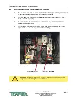
Typical electrical panel.

Typical Heater Contactor

Typical Pump Motor Starter

WARNING:


Failure to maintain the contactor may result in overheating of the 

components and catastrophic electrical failure.

Summary of Contents for Veteran VT LXG Series

Page 1: ... INSTALLATION OPERATION MAINTENANCE TEMPTEK INC 525 East Stop 18 Road Greenwood IN 46142 317 887 6352 fax 317 881 1277 Service Department fax 317 885 8683 www Temptek com E mail sales Temptek com Models with LXG Series Instrument Model Serial Number ...

Page 2: ......

Page 3: ...th LXG SERIES INSTRUMENT COVERING INSTALLATION OPERATION MAINTENANCE TEMPTEK INC 525 East Stop 18 Road Greenwood IN 46143 Phone 317 887 6352 Fax 317 881 1277 Service Department fax 317 885 8683 www Temptek com E mail sales Temptek com ...

Page 4: ... 30 3 7 Instrument Main Menu 31 3 8 Instrument Setpoints Menu 31 3 9 Instrument Utilities Menu 33 3 10 Instrument Network Menu 34 3 11 Instrument Features menu 35 3 12 Instrument Flow Menu option 38 3 13 Instrument Options Menu 39 3 14 Instrument Machine Menu 40 3 15 Shut Down Disconnect 41 4 0 TROUBLESHOOTING 43 4 1 Unit Will Not Start Display is not Illuminated 44 4 2 Unit Will Not Start Display...

Page 5: ...chematic 75 7 3 Regulator Bypass Installation 76 7 4 Dual Zone Dolly 77 7 5 Stacking Rack 78 8 0 APPENDIX 79 8 1 Model And Suffix Coding 80 8 2 Interpretation of Process Pressure Gauges 81 8 3 Mold Purge Operation 82 8 4 Remote Auto Start Feature Configuration 84 8 5 SPI Commands 86 8 6 Communications Cable 89 8 7 Optional Alarm Operation 90 8 8 AVTTM Valve Components 91 8 9 AS5 Pump Parts List 1 ...

Page 6: ...Page 6 THIS PAGE INTENTIONALLY BLANK ...

Page 7: ...G Series Instrument Page 7 TEMPTEK INC 525 East Stop 18 Road Greenwood Indiana 46142 317 887 6352 Fax 317 881 1277 Email service Temptek com 1 0 GENERAL 1 1 Receiving Instructions 1 2 Introduction 1 3 Safety 1 4 Water Treatment 1 5 Components ...

Page 8: ...o follow the installation operation and maintenance instructions may result in damage to the unit that is not covered under the limited warranty This manual is for standard products The information contained in this manual is intended to be general in nature The information is typical only and may not represent the actual unit purchased C When calling for assistance from the Manufacturer s Service...

Page 9: ...codes that apply to the installation G Samples of Warning Labels applied to typical temperature control units 1 Alerts users to the danger of high voltage 2 Alerts the user to possible explosive danger 3 Alerts the user to a hot surface danger due to high operating temperatures 1 4 WATER TREATMENT A The fluid used in your temperature control unit will greatly effect its short and long term operati...

Page 10: ...The manufacturer recommends filtering the process water to prevent solids from plugging critical parts C It is recommended that the services of a qualified water treatment specialist be engaged to determine what water treatment is required D Advantage assumes no responsibility for equipment failures which result from untreated or improperly treated water D Do not use deionized water in this unit S...

Page 11: ...com Models with 10 16 kW heaters and 3 4 3 HP pumps typical Models with 24 34 kW heaters and 5 7 5 HP pumps typical Pump Vented Stainless Steel Cabinet Pump Motor Caster Flow Meter Optional Features Inside cooling cylinder AVTTM Cooling Valve Electrical Panel Inside stainless steel cabinet Heater Pressure Gauges Thermoformed Cover Panel Instrument Not visible in this photograph ...

Page 12: ...e 12 TEMPTEK INC 525 East Stop 18 Road Greenwood Indiana 46142 317 887 6352 Fax 317 881 1277 Email service Temptek com Process Connection Label Details process connections hook up Unit Data Tag Details unit Serial Number voltage and other important unit information ...

Page 13: ... Page 13 TEMPTEK INC 525 East Stop 18 Road Greenwood Indiana 46142 317 887 6352 Fax 317 881 1277 Email service Temptek com 2 0 INSTALLATION 2 1 General 2 2 To and From Process Connections 2 3 Water Supply Connection 2 4 Drain Connection 2 5 Electrical Connection ...

Page 14: ... a maximum pressure of 150 PSI The unit is most efficient when full size plumbing is run from the unit connections to and from the process If necessary reduce the plumbing size at your process not at the unit B Be certain all process piping materials have the equivalent or larger diameter of the particular process connection 2 2 TO AND FROM PROCESS CONNECTIONS A Connect the unit s To Process port ...

Page 15: ...r supply pressure can be determined at the unit s location by reading the unit s 0 160 PSI pressure gauges when the unit s pump motor is OFF E If water supply pressure as read on the unit s pressure gauges exceeds 75 PSI a pressure reducing valve must be installed in the water supply line refer to section 7 3 of this manual for installation information The factory recommended regulated pressure ou...

Page 16: ... drain line should not be valved However for installations with a pressurized drain system it may be necessary to install a valve in the drain line In such cases the installed valve must be fully opened after installation and the valve handle removed to prevent operating the unit with a closed drain valve The valve handle can be reattached to the valve body when it is necessary to close the valve ...

Page 17: ...tage supply is the same as the unit s voltage requirements WARNING DO NOT connect the unit to a voltage supply source not equal to the unit s voltage requirements as specified on the unit s data plate Use of incorrect voltage will void the unit s warranty and cause a significant hazard that may result in damage to the unit or serious personal injury 2 Appropriate conduit and fittings should be sel...

Page 18: ...rtain the power conductor disconnecting means and fusing are properly sized according to the unit s power supply requirements 3 Make certain all electrical connections are tightly affixed Any loose wiring connections must be tighten before engaging the power supply 4 Make certain no moisture or standing water is present inside the electrical cabinet WARNING Check that all electrical connections ar...

Page 19: ...PTEK INC 525 East Stop 18 Road Greenwood Indiana 46142 317 887 6352 Fax 317 881 1277 Email service Temptek com Power Entry Low Water Pressure Switch Control Transformer Pump Motor Con troller Terminal Strip Heater Con tactor Transformer Fuse Blocks Typical Electrical Panel ...

Page 20: ...Page 20 THIS PAGE INTENTIONALLY BLANK ...

Page 21: ...hine Start Up and Operation 3 3 Instrument Operation Quick Start 3 4 Instrument Basic Navigation 3 5 Instrument Operating Screens 3 6 Instrument Fault Screens 3 7 Instrument Main Menu 3 8 Instrument Setpoints Menu 3 9 Instrument Utilities Menu 3 10 Instrument Network Menu 3 11 Instrument Features Menu 3 12 Instrument Flow Menu option 3 13 Instrument Options Menu 3 14 Instrument Machine Menu 3 15 S...

Page 22: ...opening the water supply valve customer installed at the unit s location If a valve is not installed engage the water supply source at the plant s water supply central control point 2 Once the water supply source is open the unit will fill automatically Allow a few moments for the unit to completely fill The operator can determine the unit is properly filled when the To Process pressure gauge and ...

Page 23: ...ge is supplied to the unit the Power light on the display will illuminate b Remove the thermoformed cover panel and open the hinged electrical cabinet panel cover Note that the electrical power is engaged at this point and caution must be observed while the electrical supply is engaged and the cabinet panel is open c Locate the electric motor and identify the motor shaft inside the electric motor ...

Page 24: ...r must determine and set proper water flow rate for the most efficient and trouble free operation a Water flow rate through the process is determined by the pressure losses in the process loop Generally higher flow rates result in turbulent flow achieving maximum temperature control and lower maintenance b If the flow rate exceeds the motor HP capacity the electric motor will draw excessive amps T...

Page 25: ...ctrical cabinet panel door The panel cover is hinged and held open by a support cable Note that the electrical power is engaged at this point and caution must be observed while the cabinet panel is open b Identify the motor starter block This block consists of the motor starter contactor and the overload relay c Place an amp meter on a single power lead coming from the overload relay d Locate the ...

Page 26: ...r The process flow is now correctly adjusted The valve should remain in this position during operation 6 LOW PROCESS FLOW The minimum recommended process flow rate is 10 GPM Process restrictions may limit the flow to less than 10 GPM We recommend the addition of bypass lines to raise the flow rate to 10 GPM The best place to add bypass lines are on the extra ports on the molding machine manifold I...

Page 27: ...e soft touch buttons to navigate the available screens and select parameters 4 A System Safety Fault may prevent startup Probe cooling valve water supply pressure pump overload or high temperature limit may display once power is applied and must be corrected prior to operation 5 Adjust the setpoint to the desired value by pressing the Increment or Decrement buttons 6 The unit is ready to start whe...

Page 28: ...ion Screens Selection screens display a menu of selectable items 1 The Up button will scroll up through the menu items The screen indicators will scroll along with the pressing of the button 2 The Down button will scroll down through the menu items The screen indicators will scroll along with the pressing of the button 3 The Go button will advance to the value screen of the selected parameter 4 Th...

Page 29: ... A The instrument displays several operating screens to indicate what the unit is doing as far as heating cooling and other functions In most operating screens the To Process temperature is shown with the operation indicated under the setpoint temperature as shown in the examples below B Auto Vent Auto vent occurs when the start button is pressed and the process temperature is below 100 F factory ...

Page 30: ...t find the home position Debris or other obstructions trapped in the valve orifice can cause this fault If not the valve could be defective and should be replaced 3 High Temp If process temperature exceed 256 F the high temperature limit switch opens and the unit shuts down High temperature conditions are generally caused by inadequate water supply pressure a defective cooling valve an obstructed ...

Page 31: ...w while on the Cooling screen pressing the Select button will advance to the Main Menu 3 8 INSTRUMENT SETPOINTS MENU A Under the Setpoints menu item the values for the Process Setpoint Hi Deviation Low Deviation and Low Flow can be set or changed Digital flow rate display is an option and may not be included on your machine B Process Setpoint Use the Up or Down buttons to change the process setpoi...

Page 32: ...tpoint 200 F Lo deviation alarm will sound if the temperature cools to 195 F 1 The factory default is 10 The range for the Lo Deviation is from 0 F 50 F 2 Once acknowledged press the Back button repeatedly to return to the Setpoints screen or press the home button to return to the Home screen D Low Flow optional feature not included on all units The Low Flow value programs the controller to sound ...

Page 33: ...able To Mold Purge Message will be displayed 2 When the pump is not running and when Mold Purge is enabled refer to Section 3 13 for more information on enabling Mold Purge Mold Purge is activated by selecting the mold purge item from the Utilities menu Mold purge is started immediately When mold purge is activated the following screen will show 3 Press the back button or the stop button to stop t...

Page 34: ...ors are indicated contact the factory repair or replacement options 3 10 INSTRUMENT NETWORK MENU A Items in the Network menu include Protocol Address and Baud Rate B Protocol This is the data format for communication between the unit and the host computer Available values are SPI CCP Modbus RTU and CAMAC SPI is the standard Society of Plastics Industry Inc protocol CAC is the CAMAC protocol used o...

Page 35: ...t is 1 The selection range is from 1 10 3 Press the Select button to save the address and confirm success 3 11 INSTRUMENT FEATURES MENU A Items in the Features menu include Autovent Time Autovent Temp Pump Seal Cool Pump Seal Time and Pump Seal Temp B What is Autovent Autovent is a features built into the controller to purge air from the process system When the power button is pressed and the proc...

Page 36: ... buttons to select the temperature of the autovent This is the temperature which if the process temperature is below will initiate an autovent on startup The range is 0 F 250 F The factory default is 100 F 3 Press the Select button to save the Autovent temp and confirm success E What is Pump Seal Cooling Pump seal cooling is a feature that automatically cools the unit to a preselected temperature ...

Page 37: ...g the Stop button the Pump Seal Cooling will initiate For example if the feature is set at 54 seconds the Pump Seal Cooling will continue for 54 seconds 1 Press the Select button to select Pump Seal Time item 2 Use the Up or Down arrow buttons to select the time of the pump seal cooling feature The range is 1 60 seconds The factory default is 60 seconds 3 Press the Select button to save the Pump S...

Page 38: ...alues should be factory set and should not be changed Adjust only if they are set to values other than the factory default D Calibration This allows the user to calibrate the unit s flow meter 1 Using a reliable and accurate external flow meter the user can input a calibration constant value in the screen so that the unit flow display matches the external flow meter 2 Use the Up or Down arrow keys...

Page 39: ...is done by another screen Refer to Section 3 9 B and 8 3 for more information Choose disabled to disable the mold or system purge feature 3 Once acknowledged press the Back button repeatedly to return to the Options screen or press the home button to return to the Home screen E Remote Start optional features not included on all units 1 Select Remote Start from the Options menu 2 Advance to the Rem...

Page 40: ...1 2 modulating cooling valve or 1000 1 for the 3 4 modulating cooling valve Press the Select button to save the value and confirm success C Max Setpoint This feature is useful in some application where the setpoint must never be changed above a certain temperature The Maximum Setpoint can never exceed 250 F in the unit 1 Use the Up or Down arrow keys to select the Max Setpoint and then press the S...

Page 41: ...DISCONNECT A UNIT SHUT DOWN 1 Decrease the setpoint temperature lower than 85 F and allow the unit to cool to the temperature A pump seal cooling feature can be selected from the features menu to automatically cool the unit once the stop button is pressed 2 Press the stop button 3 Relieve residual static pressure before disconnecting or servicing the unit 4 Follow all lock out tag out requirements...

Page 42: ...Page 42 THIS PAGE INTENTIONALLY BLANK ...

Page 43: ...Greenwood Indiana 46142 317 887 6352 Fax 317 881 1277 Email service Temptek com 4 0 TROUBLESHOOTING 4 1 Unit will not start Display is not Illuminated 4 2 Unit will not start Display Illuminated 4 3 Unit Stops 4 4 Unit Overheats 4 5 Unit Underheats 4 6 Pressure Relief Valve Leaks 4 7 Cooling Valve Fault ...

Page 44: ... Motor overload switch opened The electric motor is protected from overload conditions by a set of thermal overload relays These relays will open trip If the overload relay is open it must be reset before operation can continue An excessive flow condition must be isolated and corrected immediately 3 High temperature limit switch open The unit is prevented from operations at temperatures exceeding ...

Page 45: ...sure differential between the water supply and drain to achieve full cooling capacity is 10 PSI The minimum water supply pressure is 20 PSI for setpoints from 180 F and under A chart in Section 2 3 lists water supply pressures for setpoint above 180 F A drop in water supply pressure operation will cause the pump to stop and a safety fault to be displayed 2 AVTTM valve defective The instrument open...

Page 46: ...rain thus providing unwanted cooling A defective AVTTM valve should be repaired immediately 2 Heater element failure A failed heater element will not input adequate heat into the process to elevate the process water temperature The operator must check the amps at the heater contactor with the contactor energized Zero amps at the contactor indicate a failed heater or burnt wire connections The oper...

Page 47: ...r supply line This will increase the unit s internal pressure causing the pressure relief valve to leak Refer to section 7 3 for regulator installation drawing 3 Valve contamination The pressure relief valve may become contaminated with water debris causing the valve not to close properly If this is the case flushing the valve for a moment will cleanse the seat and allow it to work properly If flu...

Page 48: ...Page 48 THIS PAGE INTENTIONALLY BLANK ...

Page 49: ... 317 881 1277 Email service Temptek com 5 0 SERVICE MAINTENANCE 5 1 Pump Seal Replacement 5 2 Heater Replacement 5 3 AVTTM Cooling Valve Service 5 4 Voltage Change 5 5 Sensor Probe Service 5 6 Pressure Switch Service 5 7 Electronic Instrument Repair Policy Procedure 5 8 Temperature Probe Calibration 5 9 Heater Contactor and Pump Motor Starter ...

Page 50: ... off 3 Remove the lift off access panel and set aside 4 Remove the thermoformed panel It is attached to the stainless steel cabinet by 4 small screws figure 5 1B 5 Drain machine by removing the pump casing drain plug 6 Remove the three motor wire leads from the motor wiring terminals The operator should map the wire terminal locations to ensure correct rewiring The power cord should be removed fro...

Page 51: ...h a mild soap solution Note Oil must never be used as a lubricant as it will damage the rubber parts of the seal assembly 13 Install new stationary seal member in pump casing cavity figure 5 1H Be certain the stationary seal member is fully squared and seated in cavity 14 Slide the rotating member onto the lubricated pump shaft figure 5 1I Be certain not to damage or tear the rubber bellows assemb...

Page 52: ... the thermoformed front panel and the lift off cover D When this procedure is complete the operator may restart the unit In many cases a new pump seal will experience a small amount of leakage for a short time This is normal After a few moments the new seal will take seat and the leak will stop Stationary member Figure 5 1H Rotating member Figure 5 1I Aligning impeller and spring Figure 5 1J ...

Page 53: ...2 Disengage main power supply Verify the Power light on the display is off 3 Remove the lift off access panel and set aside 4 Drain machine The machine can be drained by removing the pump casing drain plug 5 Remove heater s junction box cover to locate wiring connections The operator should note the wiring connections to ensure correct reinstallation figure 5 2B 6 Disconnect the three power leads ...

Page 54: ...52 Fax 317 881 1277 Email service Temptek com 11 Replace the 4 heater mounting bolts Alternate to the opposite bolt while tightening 12 Reconnect the power cable to the heater terminals Be certain to tighten the power cord junction box connector Replace the junction box cover and the lift off cover panel E When complete restart the unit ...

Page 55: ...s secured by two nuts and can be removed When removed the AVTTM valve components can be viewed figure 5 3B B The conditions that require servicing of the AVTTM modulating valve are as follows 1 Motor gearbox assembly defective This condition is evidenced by non movement of the motor when prompted by the instrument This is evident when power is engaged to the instrument The instrument will turn the...

Page 56: ...or gearbox assembly is mounted to the valve bracket and is secured by 2 mounting screws NOTE It will also be necessary to remove the 2 screws that secure the micro switch to completely remove the motor since they are hard wired together 7 Remove the 2 mounting screws The motor and gearbox will now be loose Carefully separate the motor gearbox from the attached coupling from the valve assembly 8 Al...

Page 57: ...e is closed E To service the valve components continue with steps 13 20 12 Be certain the unit is totally depressurized with the unit s pressure gauges reading 0 The unit should be drained if possible 13 The valve assembly is a ball valve specially designed only to work with the AVTTM motor The valve assembly is secured to the cooling cylinder by a top plate and 4 mounting screws The drain connect...

Page 58: ...elow Once the value is back together continue with step 17 16 Aligned the valve assembly coupling to the motor gearbox and place on the cooling cylinder A gasket or seal is not required 17 Replace the top plate the micro switch mounting plate and the 4 mounting bolts Tighten the 4 mounting bolts alternating to the opposite bolts 18 Once power is reapplied the instrument will align the AVTTM modula...

Page 59: ...ther power conversions C For a field voltage changeover the following items will require replacement or rewiring 1 Heater rewiring 2 Motor rewiring 3 Transformer rewiring 4 Motor starter and overload block replace 5 Replace unit data tag with tag stating new voltage and amp rating D The qualified technician should follow this procedure to complete a field voltage changeover 1 Disengage operations ...

Page 60: ...52 Fax 317 881 1277 Email service Temptek com Wiring schematics for 240 and 480 volt heaters Revised 4 11 4 Rewire the heater to the new voltage Schematics for heater brands used in typical temperature control units are shown below Wiring Schematic for Watlow Brand Heaters 10 kw 16 kW Wiring Schematic for Tempco Brand Heaters 10 kw 16 kW ...

Page 61: ...ows the wiring schematic for 240 and 480 voltages 7 Rewire the transformer to the proper voltages as shown by the schematic on the transformer 8 Replace the motor starter and overload block Adjust the overload block settings for the current draw at the new voltage 9 Once a voltage change is complete be certain the unit is properly connected to the new voltage supply as outlined in section 2 5 of t...

Page 62: ...g the Start push button If not continue with replacement 2 REPLACEMENT Replacement of the sensor probe involves ceasing process operations as outlined in section 3 4 of this manual and removing the defective sensor probe All factory supplied replacement probes are complete with the service connection Unit with G Series instruments use one sensor probe The high temperature limit safety switch is a ...

Page 63: ...o section 3 4 in this manual Be certain proper lock out procedures are followed Also be certain system pressure is eliminated and the unit s pressure gauges read 0 pressure 2 Drain unit by removing the pump casing drain plug 3 A capillary runs from the cooling cylinder to the pressure switch Remove the capillary connection 4 The brass elbow mounted on the pressure switch must be removed 5 Remove t...

Page 64: ... C OUT OF WARRANTY SERVICE INCIDENT 1 Call the factory for diagnostic assistance 2 If a control instrument is determined to be at fault there are 3 options a Purchase a new instrument as a replacement b Send your instrument back for repair freight prepaid For a nominal fee your instrument will be repaired and returned c Purchase a new instrument and repair the old one as a back up 3 If you are sen...

Page 65: ...lace 4 Prepare an ice bath a cup of water with lots of ice You should place a digital thermometer in the ice bath to read the temperature of the bath Place the probe in the ice bath C Procedure 1 Restart the instrument according to the procedures outlined in the unit manual 2 Reduce the unit s setpoint to its lowest setting 3 The to process temperature on the display should equal the temperature o...

Page 66: ...mptek com 6 Adjust the potentiometer until the to process temperature on the display equals the temperature of the ice bath 7 When the two temperatures are equal the calibration procedure is complete 8 Stop the unit following the shutdown procedure described in the manual and place all process probes back in the unit to return to normal operation Calibration potentiometer ...

Page 67: ...tly B This is a wear item that must be routinely inspected and replaced when the contacts begin to indicate wear pitting C Failure to maintain the contactor may result in overheating of the components and catastrophic electrical failure D The standard mechanical pump motor starter must also be routinely inspected and replaced when the contacts begin to indicate wear pitting Typical electrical pane...

Page 68: ...Page 68 THIS PAGE INTENTIONALLY BLANK ...

Page 69: ...Units Veteran with LXG Series Instrument Page 69 TEMPTEK INC 525 East Stop 18 Road Greenwood Indiana 46142 317 887 6352 Fax 317 881 1277 Email service Temptek com 6 0 COMPONENTS 6 1 Mechanical System 6 2 Electrical System ...

Page 70: ...ic motor is a dual voltage 3 phase ODP motor The motor serves to turn the pump impeller creating process flow 4 Impeller The impeller is custom designed for the unit and creates the higher flow gpm from standard HP ratings 5 Pump Seal The pump seal prevents water leakage from the pump adapter The seal is made up of three items The stationary member seated in the seal cavity the rotating member pla...

Page 71: ...gauges display the system pressure To process pressure originates at the heat pump discharge cylinder From process pressure originates at the cooling cylinder The gauges accurately display system pressures from 0 to 160 PSI figure 6 1G H CASTERS The unit is mounted on 4 swivel ball bearing casters The casters allow the unit to be portable and easily move from location to location I STAINLESS STEEL...

Page 72: ...rovided with a solid state contactor rather than the standard mechanical contactor E PRESSURE SWITCH The electric panel mounted pressure switch will close when sufficient pressure is supplied to the unit 20 psi A closed pressure switch will consent the control circuit to the instrument controller to allow process operations F SENSOR PROBES The unit uses 1 sensor probe The sensor and the high tempe...

Page 73: ...s Instrument Page 73 TEMPTEK INC 525 East Stop 18 Road Greenwood Indiana 46142 317 887 6352 Fax 317 881 1277 Email service Temptek com 7 0 RELATED DRAWINGS 7 1 Physical 7 2 Circuit Schematic 7 3 Regulator Bypass 7 4 Dual Zone Dolly 7 5 Stacking Rack ...

Page 74: ...EMPTEK INC 525 East Stop 18 Road Greenwood Indiana 46142 317 887 6352 Fax 317 881 1277 Email service Temptek com 7 1 PHYSICAL To Process Drain Water Supply From Process Pressure Gauges Right Side View Left Side View Left Side View Rear View Instrument 12 1 2 26 5 8 19 1 2 ...

Page 75: ...ical drawing supplied with unit for details 7 2 CIRCUIT SCHEMATIC A DRAIN CONNECTION TO PROCESS SENSOR HI TEMP SAFETY TO PROCESS PRESSURE GAUGE TO PROCESS CONNECTION HEATER DISCHARGE TANK PUMP PUMP SEAL FLUSH DRAIN FROM PROCESS PRESSURE GAUGE PRESSURE RELIEF VALVE AVT COOLING VALVE MOTOR GEARBOX ASSEMBLY AVTTM COOLING VALVE COUPLING AVTTM COOLING VALVE BALL VALVE ASSEMBLY FROM PROCESS CONNECTION W...

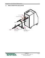
Page 76: ...5 East Stop 18 Road Greenwood Indiana 46142 317 887 6352 Fax 317 881 1277 Email service Temptek com 7 3 REGULATOR BYPASS INSTALLATION WATER SUPPLY PRESSURE REGULATOR VALVE TYPE WATTS U5B 1 2 25 75psi RANGE BYPASS VALVE TYPE WATTS BP 30 1 2 45 100psi RANGE DRAIN FROM PROCESS TO PROCESS ...

Page 77: ...TO SENTRA 2 WATER SUPPLY MANIFOLD CONNECTION DRAIN MANIFOLD CONNECTION WATER SUPPLY CONNECTION DRAIN CONNECTION DRAIN CONNECTION FROM PROCESS CONNECTION SENTRA 2 SENTRA 1 TO PROCESS CONNECTION Molders often need to run different temperatures on each mold half to produce the best quality part Advantage can provide a dual zone dolly that holds two standard single zone temperature control units to me...

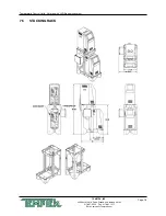
Page 78: ...Temperature Control Units Veteran with LXG Series Instrument Page 78 TEMPTEK INC 525 East Stop 18 Road Greenwood Indiana 46142 317 887 6352 Fax 317 881 1277 Email service Temptek com 7 5 STACKING RACK ...

Page 79: ...k com 8 0 APPENDIX 8 1 Model and Suffix Coding 8 2 Interpretation of Process Pressure Gauges 8 3 Mold Purge Operation 8 4 Remote Auto Start Feature Configuration 8 5 SPI Commands 8 6 Communications Cable 8 7 Optional Alarm Operation 8 8 AVTTM Valve Components 8 9 AS5 Pump Parts List 1 2 hp to 1 hp 8 10 AS5 Pump Parts List 1 5 hp to 3 hp 8 11 Standard SK G English Configuration ...

Page 80: ...200 75 GPM 2 HP 300 80 GPM 3 HP 500 90 GPM 5 HP 750 100 GPM 7 1 2 HP Control Instrument LXG LXG series instrument LXT LXT series instrument The data tag on your Sentra Temperature Control Unit provides general information about the unit Compare the information below with your data tag for more information about your unit Some data tags may have other or different information If you need specific i...

Page 81: ...erated circulating pressure which is also equal to the pressure drop across the process C PUMP ROTATION INDICATION If the pump is running and both gauges are close to same value it is likely that the pump is rotating backward or the pump is generating such a high flow that an overload condition will result D PUMP MOTOR OVERLOAD CONDITION If the P is low with the pump rotating correctly then the fl...

Page 82: ... to the Main Menu and select Options Within the Options menu select Mold Purge Select Enable to enable the Mold purge system Press the Select button to acknowledge and save the selection D The mold purge feature is used when the pump is turned off and has been cooled to below 85 F E The operation of the mold purge is as follows see illustration 1 Stop the pump maintain electrical power to unit 2 C...

Page 83: ...ring mold purge operation LINE TO DRAIN CHECK VALVE Prevents compressed air from purging unit TO PROCESS CONNECTION CHECK VALVE Prevents water bleed to air line during normal run cycle SOLENOID VALVE Opens to purge water to drain SOLENOID VALVE Opens to allow compressed air to enter during mold purge operation COMPRESSED AIR CONNEC TION WARNING Use caution when disconnecting process lines because ...

Page 84: ...his option or it can be configured in the field C Caution When configured with auto start as described here the normal on off button will no longer function to turn the unit on and off The unit must be turned off using the installed remote on off switch D Factory installed remote or auto start feature 1 If your Sentra with G Series control instrument has been factory configured with the remote or ...

Page 85: ...7 881 1277 Email service Temptek com F To active the Remote Start features 1 Access main menu and advance to the Options menu 2 From the Options menu select Remote Start 3 Press the Select button to advantage to the Enabled Disables screen 4 Select Enabled to enable the Remote Start 5 Press the Select button to acknowledge and save the selection ...

Page 86: ...ch device must have a unique address for its device type and it must use the same data transfer rate as the other pieces of equipment in the network There are many acceptable ways used to set the device address and data rate ADVANTAGE equipment provides access to the information via the front panel operators and displays Other manufacturers may use internal DIP switches or jumpers A typical cell m...

Page 87: ...0 PROCESSING ALARM SYSTEM ALARM PROCESS ALARM MACHINE ALARM HIGH TEMPERATURE ALARM LOW TEMPERATURE ALARM LOW FLOW Temperature CONTROLLER SPI COMMANDS POLL SELECT C1 C2 C1 C2 COMMAND DESCRIPTION 20 20 20 21 Echo Controller integrity command 20 20 Version Controller version command 20 30 20 31 Setpoint Desired process temperature 20 32 20 33 High temp Hi temperature deviation alarm 20 34 20 35 Low t...

Page 88: ...MAND DESCRIPTION 20 48 20 49 Machine 15 14 13 12 11 10 9 8 7 6 5 4 3 2 1 0 MACHINE ON OFF ON OFF ALLOWED ALARM ACKNOWLEDGE POLL SELECT C1 C2 C1 C2 COMMAND DESCRIPTION 20 4A 20 4B Protected mode machine POLL SELECT C1 C2 C1 C2 COMMAND DESCRIPTION 20 70 Temperature to process 20 72 Temperature from process 20 78 Flow rate from unit GPM 20 E0 Blanket Poll Returns 20 30 Setpoint 20 32 High alarm devia...

Page 89: ...perature Control Units Veteran with LXG Series Instrument Page 89 TEMPTEK INC 525 East Stop 18 Road Greenwood Indiana 46142 317 887 6352 Fax 317 881 1277 Email service Temptek com 8 6 COMMUNICATIONS CABLE ...

Page 90: ...RE SILENCED DURING AN ALARM CONDITION BY PRESSING THE START BUTTON ON MICROPROCESSOR CONTROLLER 8 7 OPTIONAL ALARM OPERATION A The instrument is standard with a 110 volt AC alarm output The alarm output can be connected to customer provided alarm annunciation plant wide monitoring system or optional annunciation provided by the factory B Beacon Alarms used when both visual and audible alarm annunc...

Page 91: ...17 881 1277 Email service Temptek com 8 8 AVTTM VALVE COMPONENTS 8 32 Lock Nut Motor Bracket 8 32 x 1 2 Hex Head Screw Valve Coupling 8 32 x 3 4 Hex Head Screw Gear Box 4 40 x 3 4 Hex Head Screw Home Switch 4 40 Lock Nut 5 16 18 x 2 Hex Head Screw 5 16 Lock Washer 8 32 Lock Nut 5 16 18 x 3 3 8 Threaded Rod Valve Motor Valve Body Cooling Cylinder ...

Page 92: ... Ceramic 4949 AE5 AS5 6207000 MOTOR PUMP ASSEMBLY AS5 3 4HP ODP 230 460 414 Adapter iron C2 4551 AS5 771599 Pump case iron D2 1839 AS5 3444400 Tank gasket 2 3 8 A 9159 AS5 3444401 Tank gasket 4 1 2 A2 8748 AS5 4310602 Impeller B2 5264 4 5 AS5 4757862 Motor AE5 AS5 A5W 3 4HP S 2772R 5486522 Nut S 4989 AS5 5622271 O ring Case S 5091 AS5 6490000 Shaft seal 101 173 5 8 EPT 6491000 Shaft seal EPT Ceram...

Page 93: ...SEMBLY AS5 3 4HP ODP 230 460 414 Adapter iron C2 4551 AS5 771599 Pump case iron D2 1839 AS5 3444400 Tank gasket 2 3 8 A 9159 AS5 3444401 Tank gasket 4 1 2 A2 8748 AS5 4310602 Impeller B2 5264 4 5 AS5 4757862 Motor AE5 AS5 A5W 3 4HP S 2772R 5486522 Nut S 4989 AS5 5622271 O ring Case S 5091 AS5 6490000 Shaft seal 101 173 5 8 EPT 6491000 Shaft seal EPT Ceramic 4949 AE5 AS5 6207010 MOTOR PUMP ASSEMBLY...

Page 94: ...i Deviation 10 F Low Deviation 10 F Low Flow 0 GPM Network Protocol SPI Baud Rate 9600 Address 1 Features Auto Vent Time 45 Seconds Auto Vent Temperature 100 F Pump Seal Cooling Disabled Pump Seal Cooling Time 60 Seconds Pump Seal Cooling Temperature 100 F Flow Flow Disabled Flow Offset 3 GPM Flow Calibration 770 Options Mold Purge Disabled Remote Start Stop Enabled Machine Cooling Valve Size 500 ...

Page 95: ...END 2021 TEMPTEK INC RE 20210323 ...

Page 96: ......

Reviews: