Temperature Control Units : Veteran with LXG Series Instrument
Page: 71
TEMPTEK, INC.
525 East Stop 18 Road Greenwood, Indiana 46142
317-887-6352 Fax: 317-881-1277
Email: service@Temptek.com
D.
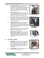
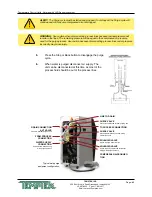
COOLING CYLINDER.
The cooling cylinder is a custom
cast tank. The tank is flanged mounted to the pump
casing. Reinforced machined bosses accept the pressure
relief valve, the “from process” pressure gauge and
pressure switch capillary connector, AVT
TM
modulating
cooling valve, the “water supply connection” and the “from
process” connection.
E.
PRESSURE RELIEF VALVE.
The pressure relief valve
is a 150 psi relief valve serving to discharge excessive
unit pressure to atmosphere.
The valve can be manually
activated by lifting the actuating lever (figure 6.1F).
F. AVT
TM
VALVE.
The AVT
TM
valve is a patented Advantage
design using a motor/gearbox assembly to open in minute
increments from 0 to 100% a custom ball valve assembly.
The AVT
TM
valve is controlled by custom programming of
the instrument (figure 6.1F).
G.
PRESSURE GAUGES.
“To” and “from” process pressure
gauges display the system pressure. “To process”
pressure originates at the heat/pump discharge cylinder.
“From process” pressure originates at the cooling cylinder.
The gauges accurately display system pressures from 0
to 160 PSI (figure 6.1G).
H. CASTERS.
The unit is mounted on 4 swivel ball bearing
casters. The casters allow the unit to be portable and
easily move from location to location.
I.
STAINLESS STEEL CABINETRY.
The stainless steel
cabinetry prevents unsightly rust and metal decay. The
electrical cabinet cover is hinged. The unit base is made
of pressed steel with galvanized zinc coating. The lift off
access panel is secured to the unit base by 5 screws
(figure 6.1G).
6.2 ELECTRICAL SYSTEM
A. INSTRUMENT.
The instrument is a custom designed and
assembled microprocessor controller. The instrument is
mounted to the electrical panel cover. The instrument
controls the cycling of the heater, motor pump and
AVT
TM
cooling valve. System and setpoint temperatures
are displayed continually. System parameters are
programmable..
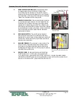
B. TRANSFORMER.
The transformer supplies 110 volts to
the controlling instrument (figure 6.2B).
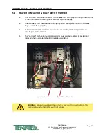
AVT modulating valve
Heater
Discharge tank
Stainless Steel Cabinetry
Typical instrument with service
connections removed
Summary of Contents for Veteran VT LXG Series
Page 2: ......
Page 6: ...Page 6 THIS PAGE INTENTIONALLY BLANK ...
Page 20: ...Page 20 THIS PAGE INTENTIONALLY BLANK ...
Page 42: ...Page 42 THIS PAGE INTENTIONALLY BLANK ...
Page 48: ...Page 48 THIS PAGE INTENTIONALLY BLANK ...
Page 68: ...Page 68 THIS PAGE INTENTIONALLY BLANK ...
Page 95: ...END 2021 TEMPTEK INC RE 20210323 ...
Page 96: ......


