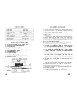
background image

4  


PRODUCT DESCRIPTION 

The  TENMA   21-19650  is  a  high  performance  induction  heating  

soldering  iron.  It  is    equipped  with  a  quick  heating  induction  heater 

and specially designed tips suitable for advance lead free soldering . 

The  separate  tip  and  heater  design  offers  cost  efficiency  and  easy 

replacement of tips.   
 

It  has  various  functions  and  features  such  as  digital  offset, 

System  lock-out  ,  quick  jump,  Temperature  Scale  selection,  auto 

sleep and auto calibration.  


These  functions will be discussed in greater detail together with 

the complete features in the succeeding sections of this manual. 


PACKAGE INCLUSION 

1 unit 21-19650 Main Station 

1 pc.  Soldering Iron 

1 pc.  Soldering Iron Stand 

1 pc.  Power Cord 

1 pc.  Instruction Manual 


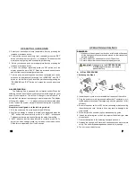
** Kindly refer to soldering iron stand installation on page 7  for parts and instructions. 

13  


OPERATING GUIDELINES 

With  the  auto-calibration  adaptor  attached,  tip  calibration  can  be 

done via the following method: 

1.  While the unit is ON , press and hold the set button. 

2.  Wait for the display to change to “A###”, then repeatedly press the 

“SET” button until the prefix “G” or “G###” is displayed. This denotes 
that we are now in autocalibration mode. 

3.  Place the tip of the soldering iron to the sensor of the auto-

calibration adaptor. Wait for the temperature reading to stabilize. 

4.  Press the increase button to start auto calibration. 

5.  The display would jump to “A###”. The number shown indicates the 

system has automatically calibrated the required digital offset pa-

rameters for the tip.  

6.  To save the newly calculated digital offset configuration, repeatedly 

press the SET button until the display shows the word “SAVE”. 
Press the increase button to save and exit from the system 

configuration mode. 


Note: During system configuration mode if it is decided that the 

recently changed setting should not be saved into system 

memory, repeatedly press the set button until the display shows 

the word “CncL” (cancel). Press the increase button to exit system 

configuration mode without saving the most recent changes 

made. 

Summary of Contents for 21-19650

Page 1: ... there are combustible materials do not apply to the same place for a long time do not use in presence of an explosive atmosphere be aware that heat may be conducted to combustible materials that are out of sight place the appliance on its stand after use and allow it to cool down before storage do not leave the appliance unattended when it is switched on Rohs Correct Disposal of this product This...

Page 2: ...y connected display still shows PLUG SOLUTION The heating element may have been damaged Replace heating element Or check the wirings of the solder iron pen PROBLEM 3 DISPLAY SHOWS WARNING MESSAGES Description Display shows the word TiP SOLUTION This indicates that the tip is not inserted or is not properly attached to the soldering iron CASE 2 Display shows the word OFF SOLUTION The system has gon...

Page 3: ...unit will not be used for long periods it is advised to power down the unit and un plug from the mains 5 Inspecting and cleaning the tip Set the temperature to 250o C When the temperature stabilizes clean the tip and check its condi tion If the tip is badly worn or deformed replace it If the solder plated part of the tip is covered with black oxide apply fresh solder containing flux and clean the ...

Page 4: ...one via the following method 1 While the unit is ON press and hold the set button 2 Wait for the display to change to A then repeatedly press the SET button until the prefix G or G is displayed This denotes that we are now in autocalibration mode 3 Place the tip of the soldering iron to the sensor of the auto calibration adaptor Wait for the temperature reading to stabilize 4 Press the increase bu...

Page 5: ...il ized if attached to our separate auto calibration adaptor For detailed information on how to utilize this feature please refer to the manual pro vided with the auto calibration adaptor 5 SAFETY PRECAUTIONS Check each component after opening the package to make sure everything is in good condition If there are any suspected damage do not use the item and report the issue to your vendor Turn OFF ...

Page 6: ...n The display will show Pin when system lock feature is enabled A PIN code is required to regain access to the system s settings and temperature adjustment This PIN code is user defined and this feature can be disabled To activate the system lock feature and select desired PIN code 1 With the unit turned On press and hold the SET button 2 Wait for the display to change to A then repeatedly press t...

Page 7: ...s and hold the SET button 2 Wait for the display to change to A then repeatedly press the SET button until a number with prefix d or d0FF is displayed This denotes that we are now configuring the sleep timer setting 3 d0FF indicates that the sleep function is currently turned off To adjust the timer settings press the increase or decrease button Sleep timer is adjustable from 1 to 60 minutes 7 OPE...

Page 8: ...onfiguring the digital offset of the system A display like A000 indicates that the digital offset is currently set at neutral 3 Press the increase and decrease button to adjust the digital offset A negative number denotes a negative offset and a positive number denotes a positive offset 9 OPERATING GUIDELINES 5 Adjust the offset number until the external temperature sensor reading is equal to our ...

Reviews: