Tenma 72-6851 & 72-6853 Instruction manual
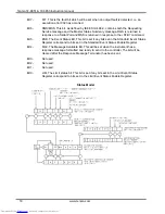
bit 6 =
1
bit 5 =
1 Parallel poll enable
bit 4 =
0
bit 3 = Sense - sense of the response bit; 0 = low,
1 = high
bit 2 =
?
bit 1 =
? bit position of the response
bit 0 =
?
Example. To return the RQS bit (bit 6 of the Status Byte Register) as a 1
when true and a 0 when false in bit position 1 in response to a
parallel poll operation send the following commands
∗
PRE 64
<pmt>,
then PPC followed by 69H (PPE)
The parallel poll response from the generator will then be 00H if RQS is 0 and 01H if RQS is 1.
During parallel poll response the DIO interface lines are resistively terminated (passive
termination). This allows multiple devices to share the same response bit position in either wired-
AND or wired-OR configuration, see IEEE 488.1 for more information.
Status Reporting
This section describes the complete status model of the instrument. Note that some registers are
specific to the GPIB section of the instrument and are of limited use in an RS232 environment.
Standard Event Status and Standard Event Status Enable Registers
These two registers are implemented as required by the IEEE std. 488.2.
Any bits set in the Standard Event Status Register which correspond to bits set in the Standard
Event Status Enable Register will cause the ESB bit to be set in the Status Byte Register.
The Standard Event Status Register is read and cleared by the
∗
ESR? command. The Standard
Event Status Enable register is set by the
∗
ESE <nrf> command and read by the
∗
ESE?
command.
Bit 7 -
Power On. Set when power is first applied to the instrument.
Bit 6 -
Not used.
Bit 5 -
Command Error. Set when a syntax type error is detected in a command from the
bus. The parser is reset and parsing continues at the next byte in the input stream.
Bit 4 -
Execution Error. Set when an error is encountered while attempting to execute a
completely parsed command. The appropriate error number will be reported in the
Execution Error Register, as listed below:
001
Checksum error in non-volatile ram at power on.
002
Output stage failed to respond - possibly a system fault.
003
Output stage trip has occurred - attempting to recover.
100
Maximum set voltage value exceeded.
101
Maximum set amps value exceeded.
102
Minimum set voltage exceeded.
103
Minimum set amps value exceeded.
104
Maximum delta voltage value exceeded.
105
Maximum delta amps value exceeded.
16
www.tenma.com
electronic components distributor


