4
●
Programmable power supply with a digital interface
●
Three separately adjustable linear outputs
●
The 192×64 LCD Display can display multiple settings and measurements simultaneously
●
Windows-based interface for user-friendly operation
●
High stability and low drift
●
Over Voltage, Current, and Temperature protection
●
Intelligent fan control adjusts with output power
●
Built-in warning buzzer
●
Accurate user calibration software
●
Space-saving design
●
Fine adjustment knob
●
90 setting memory
●
Parallel, series, and independent operation modes
●
1-second timing resolution.
13
PRODUCT INTRODUCTION
Product Overview
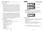
72-8795 Programmable Power Supply is controlled by a Micro Processor
Unit (MPU) that is designed for a communication interface by RS-232 or USB to
computer to enable advanced testing and power delivery by programmable control.
T h e v o l t a g e a n d c u r r e n t a r e c o n t r o l l e d by a 12 b i t D / A C o n v e r t e r
with high resolution and accuracy. Also, the digital inter face provides
a speedy, precise and convenient input of information controlled by intuitive controls.
The adjustment of voltage/current is made by software calibration, eliminating
potential manual fault, that increases the precision of the instrument.
Over Voltage Protection (OVP) and Over Current Protection (OCP) can be set with the
software and utilized by the hardware to achieve precise, instant protection
t o p r e v e n t d a m a g e a n d i n c r e a s e t h e u s e r s ’ s a f e t y .
We warrant this unit to be free from manufacturer material and workmanship defects
for one year from the original date of purchase within North America. If the unit fails
during normal use withing the warranty period, please contact the authorized reseller
of this product for repair or replacement. This warranty does not apply to defects
and failure resulting from customer actions, such as mishandling, misapplication,
overloading power or current, unauthorized repair, or any modification. The reseller
and manufacturer hold the right to deny any warranty claims based on these reasons,
or to fulfill warranty with a similar product at a similar value.
Additional Features
CH1
OFF
CH1
OFF
3 2 . 0 0 V
3 2 . 0 0 V
3 2 . 0 0 V
3 2 . 0 0 V
0 6
. 0 0 V
0 6
. 0 0 V
3 . 0 0 0 A
3 . 0 0 0 A
3 . 0 0 0 A
3 . 0 0 0 A
S h i f t
S h i f t
PARA
SERI
OCP
OFF
OCP
OFF
3 . 0 0 0 A
3 . 0 0 0 A
CH3
OFF
CH3
OFF
CH2
OFF
CH2
OFF
OCP
OFF
OCP
OFF
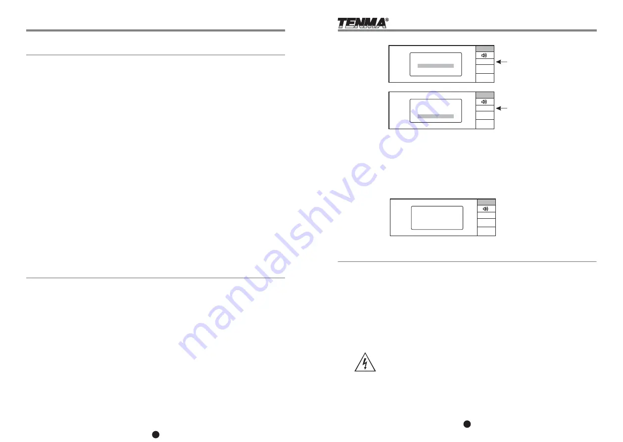
OUT SET
INDEP OUT
PARA OUT
SERIES OUT
OUT SET
INDEP OUT
PARA OUT
SERIES OUT
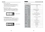
8. Communication Setting
Press
[SHIFT][COMM]
to access the interface for the communication setting.
Use the key directions to move the cursor to the corresponding value place. You
can set the power address, communication speed and data bit by using the rotary
knob to change the values. Press
[ENTER]
to store and exit.
CH1
OFF
3 2 . 0 0 V
3 2 . 0 0 V
0 4
. 1 0 V
2 . 0 0 0 A
2 . 0 0 0 A
S h i f t
INDEP
OCP
OFF
2 . 0 0 0 A
CH3
OFF
CH2
OFF
OCP
OFF
INTERFACE
ADDR
:
001
BAUD
:
19200
DATA: 9
GENERAL MAINTENANCE
General Maintenance
To avoid electrical shock, do no perform any service or repair other than those outlined in these
operating instructions. Any additional attempts at servicing or modifying this unit voids all
manufacturer warranty and liability.
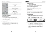
1. Fuse Replacement
If the fuse blows, the display will not light and the power supply will not operate.
Replace the fuse with a compatible rated fuse. The unit was originally supplied with a 5 Amp
250V glass type fuse. The fuse compartment is located at the AC plug terminal
WARNING:
Replace fuse only with 250V fuse of the specific type and
rating, and always disconnect power cord before replacing fuse.
Parallel Output Mode
Serial Output Mode


