background image

9


F/C (STEP)


RECALL

(

STORE)


AUTO(COMM)


INDEP


(PARA/SER)


OCP


(

OVP RESET)


SHIFT


CONTRAST


OUTPUT


Data entry, 

Value output

ENTER 


AC Power Socket


Cooling Fan


Interface


8

POWER


DISPLAY


CH1 OUT


CH2 OUT


CH3 OUT


GND Terminal


Rotary Knob


V  SET(CH1)


I  SET(CH2)


OVP SET(CH3)


26

27

28

29

, “0”

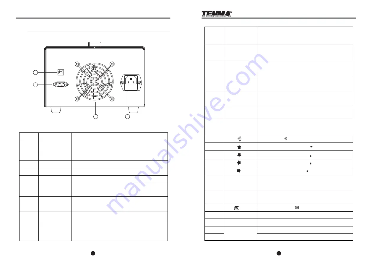
Layout of Rear Panel

Function description as below:

Toggle main unit power on/off

Displays output  voltage and current, power settings,

 and volume, OVP, and OCP statuses

CH1 output terminals

CH2 output terminals

CH3 output terminals

Ground terminal connecting to CASE

Press and turn to incrementally adjust power  settings;

turn to cycle through menus and setting

1

2

3

4

5

6

7

8

9

10

Set Output voltage;  

[SHIFT] [CH1]


to select Channel 1 settings


Set Output current: 

[SHIFT] [CH2] 

 to select Channel 2 settings


Set Over-voltage Protection  value: 

[SHIFT] [CH3] 

 to select Channel 3 settings

FUNCTION LAYOUT

FUNCTION LAYOUT

11

12

0~9

.

 , ENTER

Cooling Fan

USB communication interface

RS232C communication interface

AC power input terminal

Press 

  to restore factory settings

[SHIFT] [     ]

Turn on or off output; if a channel is selected,

you can turn on or off the corresponding channel; 

when you select no channel, all channels on turned on or off.

Move the cursor upward by pressing 

[   ] 

in the storage settings

Move the cursor on the right by pressing 

[   ] 

in the storage settings


[SHIFT] [     ] 

to toggle the audible alert on or off.

to access the display contrast settings, 

use the rotary  knob to adjust; press

 [ENTER]

  to exit setting.


[SHIFT][CONTRAST] 

Press first to access the second assigned function 

of a button. 

Turn OCP on or off;

[SHIFT][RESET] 

key to clear over-voltage protection

Switch to independent output mode;

[SHIFT][PARA/SER]

 to switch to Parallel or Serial output mode 

Toggles automatic execute mode;

[SHIFT] [COMM]

 to access the interface 

of the communication settings.

Recall the stored settings;


[SHIFT][STORE] 

to edit and save channel settings.

Change incremental tuning value of the rotary knob; 

[SHIFT][Step] to change the incremental steps

of the rotary knob

13

14

15

16

17

18

19

20

21

22

23

24

25

26

27

28

29


Move the cursor downward by pressing 

[   ] 

in the storage settings

Move the cursor on the left by pressing 

[   ] 

in the  storage settings

Summary of Contents for 72-8795

Page 1: ...User s Manual 72 8795 PROGRAMMABLEDC POWERSUPPLY 405 S Pioneer Blvd Springboro OH 45066 mcmelectronics com ...

Page 2: ...72 8795 PROGRAMMABLEDC POWERSUPPLY Programmable DCPowerSupplySeries Thanks for using our products Please read this manual thoroughly before operation ...

Page 3: ...ursor down until the calibration interface reads Output Calibration Move the cursor to a corresponding channel and adjust the output voltage by using the rotary knob to equal 32V reading on the voltmeter Press ENTER and then the calibration data of the corresponding channel is stored Move the cursor down into the calibration of the other channels with the same procedure with channels 1 and 2 at 32...

Page 4: ...gh humidity high radiation and areas with magnetic interference F 104 F Safety Precautions 2 Adjustment And Calibration 2 1 1 Preparation a Power unit on and allow 30 minutes to warm up before calibration b Ambient temperature 23 5 C Humidity Less than RH80 c Select a reliable six and a half digital voltmeter with a current test range more than 5A 2 1 2 Output Calibration Steps Step 1 Press SHIFT ...

Page 5: ...ontact the authorized reseller of this product for repair or replacement This warranty does not apply to defects and failure resulting from customer actions such as mishandling misapplication overloading power or current unauthorized repair or any modification The reseller and manufacturer hold the right to deny any warranty claims based on these reasons or to fulfill warranty with a similar produ...

Page 6: ...knob to select the desired output mode Press ENTER to confirm and return to the main screen When the unit operates in series or parallel output modes channel 2 operates as the master CH1 and CH2 will output the settings for Ch2 In independent mode each channel will output it s own individual settings 72 8795 3mV AC 5 3mA 10mV Resolution 100ppm 3mV 100ppm 3mA 10 90 100ms 90 10 10 10 rated load ms T...

Page 7: ...he packaging or a direct replacement Example Set current at 1 500A Press I SET 1 0 0 0 ENTER If the load current through output terminals exceeds the setting value the instrument will operate in the C C mode if load current does not exceed the setting value the instrument will operate in the C V mode 3 Over Current Protection Setting Press OCP to turn on the OCP mode OCP mode is can be turned off ...

Page 8: ...el by pressing SHIFT CH to set the cursor to toggle that channel Method 1 Set output voltage by pressing V SET and using the number and decimal keys to key in voltage value then press ENTER Method 2 Press V SET press the rotary knob once and turn the rotary knob to input voltage value The output voltage setting is changed immediately during selection Press ENTER to save the voltage setting Example...

Page 9: ...nput terminal Press to restore factory settings SHIFT Turn on or off output if a channel is selected you can turn on or off the corresponding channel when you select no channel all channels on turned on or off Move the cursor upward by pressing in the storage settings Move the cursor on the right by pressing in the storage settings SHIFT to toggle the audible alert on or off to access the display ...

Reviews: