background image

ELECTRICAL DIAGRAMS

Tennant  1500  (02–97)

32

WIRE DIAGRAM

33

58

35

82

33

58

33

58

33

58

31

31

31

31

36

16

16

38

16

30

76

76

16

38

26

24

24

50

50

50

50

11

32

13

15

17

28

44

14

52

60

56

54

64

74

72

62

70

32

7

8

18

5

5

12

12

20

21

18

27

3

6

6

7

24

66

66

14

4

10

10

34

60

64

62

46

19

41

24

17

BLK

RED

BLU

RED

RED

BLK

RED

BLK

BLK

BLK

BLK

RED

RED

RED

BLU

BRN

BLK

BLU

BRN

YEL

BLK

BLK

ORG

ORG

GRN

GRN

GRN

RED

RED

RED

RED

RED

BLU

RED

GRN

GRN

RED

RED

GRN

RED

YEL

RED

GRN

GRN

BLU

BRN

BRN

BLU

BRN

BLK

BLK

BLK

BLK

BLK

BLK

ORG

WHT

RED

RED

GRN

ORG

WHT

BLU

ORG

ORG

4

RED

BLK

RED

4

RED

3

9

27

BLK

BLK

BLK

BLK

RED

38

RED

48

BLU

23

BLK

9

BLK

BLK

36

38

RED

48

BLU

MAIN

ACTUATOR

MOTOR

DRIVE
MOTOR

T2

T1

M1

M2

60
AMP

15

AMP

VACUUM

MOTOR

PUMP

BRUSH
MOTOR

+

+

-

-

+

-

UP

ACTUATOR

DOWN

BATTERY

METER

4.7K

50K

ADJUSTABLE

FORWARD

DIRECTION

SWITCH

F

R

50K

LOCKABLE

REVERSE

ROLL

SWITCH

(2) 12 VOLT
BATTERIES

24 VDC

BRUSH\

PUMP

VACUUM

SPEED
CONTROL
BOARD

SOLUTION
SOLENOID

HARNESS
CONNECTOR

VACUUM/

DRIVE
CIRCUIT
BREAKER

MAIN
CIRCUIT
BREAKER

CHARGER

PLUG

CHARGER

CUTOFF

SWITCH

POSITIVE

STANDOFF

NEGATIVE

STANDOFF

BRUSH

ROLL

SWITCH

G

MAIN

VACUUM

G

G

GRN

RED

Summary of Contents for 1500

Page 1: ...rpet Extractor 1500 Model No 607647 607653 Pac Operator and Parts Manual 607648 Rev 00 11 99 FAX 1 800 678 4240 CUSTOMER SERVICE 1 800 982 7658 TENNANT COMPANY Commercial Products 12875 RANSOM STREET HOLLAND MI 49424 U S A ...

Page 2: ...nstall Date Serial No 1999 Tennant Company Printed in U S A Specifications and parts are subject to change without notice TABLE OF CONTENTS SAFETY PRECAUTIONS 3 MACHINE COMPONENTS 4 CONTROL PANEL SYMBOLS 4 MACHINE INSTALLATION 5 UNCRATING MACHINE 5 INSTALLING BATTERIES 5 MACHINE SETUP 6 FILLING SOLUTION TANK 6 ADJUSTING CONTROL GRIP HEIGHT 6 MACHINE OPERATION 6 WHILE OPERATING MACHINE 7 CIRCUIT BR...

Page 3: ...ure all safety devices are in place and operate properly 3 When using machine Go slow on inclines and slippery surfaces Use care when reversing machine Always follow safety and traffic rules Report machine damage or faulty operation immediately Follow mixing and handling instructions on chemical containers 4 Before leaving or servicing machine Stop on level surface Turn off machine 5 When servicin...

Page 4: ...ble Control Console Levers 15 Recovery Tank Drain Hose 16 Solution Tank Drain Hose 17 19L 5 Gal Increment Markers 18 Rear Fill Port 19 Inline Solution Filter Strainer 20 Accessory Solution hose Coupler 21 Accessory Vacuum Hose Connecter 22 Recovery Tank 23 Recovery Tank Lid 24 Solution Tank 25 Solution Tank Fill Door 26 Battery Compartment 27 Charger Plug 28 Drive Wheels 29 Rear Casters 30 Wall Ro...

Page 5: ...les Avoid contact with battery acid Battery Specifications Two 12 volt deep cycle batteries Consult with an Authorized Distributor for specific batteries Maximum battery dimensions are 178 mm 7 in W x 381 mm 15 in L x 356 mm 14 in H 1 Turn all switches to the OFF position 2 Carefully hinge open recovery tank to access battery compartment Remove loose battery cable from compartment Figure 1 FIG 1 3...

Page 6: ...nd handling instructions on chemical containers ATTENTION Use only recommended cleaning chemicals DO NOT use substitutes Consult an authorized distributor to assist you with the recommended cleaning chemicals ADJUSTING CONTROL GRIP HEIGHT The machine has three control grip height settings 1 Locate two spring loaded levers below console 2 Squeeze levers together and lift or lower control grips to a...

Page 7: ...eed to maintain control when turning machine 4 Overlap each pass by 50 mm 2 in 5 Before reaching end of cleaning path turn off pump switch and continue to drive machine forward to extract solution 6 Periodically check battery meter discharge level When needle drops to the red zone recharge batteries ATTENTION Do not continue to run machine when battery meter needle is in the red zone battery damag...

Page 8: ...m hose at rear of machine and replace with accessory vacuum hose Figure 10 FIG 10 4 Connect solution hose to accessory tool coupler located at lower rear of machine Figure 11 FIG 11 5 Connect accessory tool to solution hose and vacuum hose Figure 12 FIG 12 6 Turn on main pump and vacuum switches 7 Take accessory tool and begin cleaning at top of area and work backwards toward machine WARNING Flamm...

Page 9: ...To drain recovery tank perform the following steps ATTENTION If recovery tank is not emptied between fill ups foam or water will enter vacuum standpipe and damage vacuum motor Float shut off screen will not keep foam out of standpipe Vacuum damage due to foam or water is not covered by warranty 1 Remove drain hose from holder position hose over floor drain and twist off drain hose plug To complete...

Page 10: ...harged for lengthy periods ATTENTION Do not continue to run machine when battery meter needle is in the red zone battery damage will result WARNING Batteries emit hydrogen gas Explosion or fire can result Keep sparks and open flame away Keep battery compartment open when charging FOR SAFETY When servicing machine wear protective gloves when handling batteries or battery cables Avoid contact with b...

Page 11: ...vicing machine disconnect battery connections before working on machine ATTENTION Contact an Authorized Service Center for machine repairs Machine repairs performed by other than an authorized person will void your warranty DAILY MAINTENANCE Every 4 Hours of Operation 1 Recharge batteries if discharged below 50 2 Remove float shut off screen and rinse off Screen is located in recovery tank Figure ...

Page 12: ...ctions on chemical containers c Turn on the main and pump switches d Over a floor drain rotate control grips and hold for one to two minutes e Shut off power and let machine set overnight to allow acetic acid solution to breakdown alkaline buildup f Next day operate pump to disperse remaining acetic acid solution g Then rinse out solution tank and solution lines with clean water h Reset drive circ...

Page 13: ...da solution to enter battery cells c Use wire brush to clean terminal post and cable connections d After cleaning apply a coating of clear battery post protectant to terminals and cable connections 4 Check for loose or worn cables Replace if worn ADJUSTING BRUSH HEIGHT Brush height is factory preset and should not require any adjustment If brush height adjustment is necessary follow steps below Pr...

Page 14: ...stment nut clockwise for more pick up head pressure or counter clockwise for less Do not remove nut Figure 28 FIG 28 STORING MACHINE 1 Before storing machine be certain to rinse tanks and drain machine of all water 2 Store machine in a dry area 3 Remove recovery lid to promote air circulation 4 Raise the brush pickup head off the floor 5 If storing machine in freezing temperatures be certain to ci...

Page 15: ...ct Service Center Carbon brushes worn Contact Service Center Drive motor does not operate Drive motor circuit breaker has tripped Determine cause and reset breaker operate Faulty speed control board or connection Contact Service Center Faulty solenoid Contact Service Center Faulty drive motor Contact Service Center Faulty wiring Contact Service Center Worn carbon brushes Contact Service Center Dri...

Page 16: ...vice Center Vacuum hose connections are loose or hose has a hole Push hose cuffs firmly on connections Replace hose if damaged Vacuum hose is clogged with debris Remove clogged debris Recovery tank inlet hole is obstructed Empty recovery tank and tilt tank sideways to access inlet hole remove obstruction Tank gasket is defective Replace gasket Drain hose plug is loose Tighten drain plug Recovery t...

Page 17: ...Fixed Reverse CLEANING SPEED MAX 418 05m2 4 500 sq ft per hour CLEANING PATH WIDTH 559 mm 22 in PAD PRESSURE Variable 36 68Kg 80 150 lbs SOLUTION PUMP 6 9 bar 100 psi max 24V DRIVE SYSTEM Transaxle 2 h p 24V BRUSH MOTOR 2 h p 2000 rpm 24V 8A 192W VACUUM MOTOR 1 h p 2 stage 7 2 24V 30A 720W WATERLIFT 2057 mm 81 in BATTERIES 2 12V 215AH RUN TIME PER CHARGE Up to 4 5 hours DECIBEL RATING AT OPERATOR ...

Page 18: ...PARTS LIST Tennant 1500 05 99 18 SOLUTION TANK GROUP 30 2 3 28 13 14 15 16 18 17 19 20 24 26 27 21 22 18 19 23 29 31 33 34 31 38 37 36 35 42 43 4 6 5 1 32 40 41 39 40 39 25 7 9 11 10 8 9 10 12 12 10 9 7 ...

Page 19: ...TUBE 1 18 140027 WASHER FLAT 2 19 140015 WASHER LOCK 2 20 200 031 486 SCREW M08X16MM 2 21 230925 SUPPORT RECOVERY TANK 1 22 140116 BUSHING 1 REF PART DESCRIPTION QTY 23 140275 SCREW M8X1 25X16MM 1 24 600476 STRAP PLUG 1 25 621324 PLUG EXPANSION 1 26 140011 WASHER FLAT 1 27 140350 SCREW 10X1 2 1 28 603233 DECAL BATTERY DIAGRAM 1 29 607552 TANK SOLUTION TEAL 1 30 608155 DECAL 1500 2 31 150529 HOSE B...

Page 20: ...PARTS LIST Tennant 1500 05 99 20 RECOVERY TANK GROUP 28 15 26 20 23 24 15 22 1 2 30 12 3 4 5 6 11 9 10 13 15 14 16 15 14 13 14 15 13 8 7 34 35 33 32 36 17 18 19 25 27 31 21a 21 ...

Page 21: ...27 WASHER FLAT 1 18 140015 WASHER LOCK 1 19 200 031 488 SCREW M08X20MM 1 20 100001 GASKET VAC MOTOR 1 REF PART DESCRIPTION QTY 21 602656 MOTOR VAC 7 2 2 STAGE 24 VDC 1 604403 CARBON BRUSH SET OF 2 2 22 200 031 441 SCREW M6X1 0X25 HXHDCP 1 23 130192 TERMINAL MALE 1 4 10 12 10 2 24 603963 SPACER 6 5X12 7X41 2 2 25 578729 DECAL READ MANUAL 1 26 603962 SCREW M6X1 0X60 HXHDCP 2 27 120906 DECAL IMPORTAN...

Page 22: ... 6 7 8 9 18 10 19 20 3 4 5 17 10 19 20 10 10 12 11 40 13 15 14 16 21 22 23 24 22 25 26 27 28 29 28 30 31 22 21 32 34 36 37 30 38 39 27 33 37 42 41 37 24 22 2 22 26 25 9 24 21 43 22 25 48 45 7 8 9 46 48 49 47 44 15 14 35 11 28 30 31 27 28 22 11 11 24 ...

Page 23: ...ER FLAT 17 23 602567 BRACKET SPRING 1 24 602882 BUSHING 8 25 140024 WASHER LOCK 6 REF PART DESCRIPTION QTY 26 140352 SCREW M12X1 75X25 4 27 140564 BOLT SHOULDER 3 8X3 4 4 28 140036 WASHER FLAT 4 29 603044 PLATE ACTUATOR LIFT 4 30 140027 WASHER FLAT 1 31 140546 NUT NYLOCK 4 32 600305 BRACKET LIFT EXTRACTOR 2 33 602977 BRACKET MOUNT CARPET TOOL 1 34 602565 SPRING CARPET TOOL 1 35 140221 SCREW 5 16 1...

Page 24: ...LINDER 1 8 140554 SCREW 1 4 20X3 4 4 9 100049 SEAL BRUSH BEARING 2 10 140125 BEARING BRUSH 2 11 230261 BLOCK BEARING 2 REF PART DESCRIPTION QTY 12 100005 GASKET BEARING BLOCK 1 13 230408 PULLEY BRUSH 1 14 140548 NUT 5 16 1 15 230406 SHAFT BRUSH 1 16 602965 MOTOR BRUSH DRIVE 24 VDC 1 17 130096 TERMINAL MALE DSCNT 16 14 2 18 230411 BRACKET BRUSH MOTOR 1 19 140518 NUT KEP 10 32 2 20 140859 SCREW SET ...

Page 25: ...600606 END BELL TRANSAXLE MOTOR 1 3 630504 CARBON BRUSH 2 4 630503 CAP 2 5 640013 WHEEL 8 2 6 140000 WASHER FLAT 8 REF PART DESCRIPTION QTY 7 630268 NUT 8 8 612 255 000 SCREW M10X35MM 4 9 140333 WASHER LOCK 4 10 602881 BRACKET TRANSAXLE MOTOR 2 11 600304 SPACER AXLE 3 4X4X1 4 4 12 602883 SPACER 3 4X4X1 8 2 ASSEMBLY INCLUDED IN ASSEMBLY ...

Page 26: ...02 97 26 PLUMBING GROUP 13 3 1 2 5 6 4 8 7 9 10 12 11 17 15 13 13 14 8 7 8 18 19 16 20 B D D C C B A A 1 28 27 19 2 21 26 20 22 23 24 25 30 31 32 37 10 9 34 35 2 36 33 39 42 35 38 2 36 41 40 29 PUMP BREAKDOWN 47 32 43 44 45 46 ...

Page 27: ...OUPLER 1 25 150422 ELBOW STREET 1 8MX1 8F 45 1 26 230407 MANIFOLD SPRAYBAR 1 REF PART DESCRIPTION QTY 27 150208 PLUG 2 28 201011 NOZZLE TWISTOUT 80015 6 29 201013 TIP REPLACEMENT 80015 6 30 140899 SCREW 10 24X1 1 4 2 31 140012 WASHER FLAT 2 32 603031 PUMP 100 PSI 24 VDC 1 33 140552 NUT NYLOCK 2 34 150006 BUSHING 1 35 150409 ELBOW 90 1 36 607305 TUBING 3 8 X 30 GRAY VINYL 1 37 150425 ELBOW 3 8MX1 2...

Page 28: ... Tennant 1500 05 99 28 CONSOLE GROUP 27 1 2 3 10 5 6 7 8 9 12 13 11 12 14 1 15 38 36 20 42 43 21 16 17 26 23 22 24 25 30 35 31 32 33 34 29 37 36 40 18 44 19 28 Wire Harnesses 41 45 35 4 39 36 SEE ELECTRICAL GROUP ...

Page 29: ...MM 2 21 630304 SCREW M4X35MM 2 22 230715 TUBE HANDLE ADJUSTMENT 1 23 230649 PIN HANDLE ADJUSTMENT 2 REF PART DESCRIPTION QTY 24 230710 PIN HANDLE LOCK 2 25 140415 SPRING LOCK PIN 1 26 140155 BUSHING 2 27 601110 KNOB SPEED CONTROL 1 28 603007 BUSHING SNAP 1 29 602886 PIN SPRING RETURN 1 30 601118 SPRING EXPANSION 1 31 140830 SCREW 6 32X1 5 8 2 32 140019 WASHER LOCK 2 33 27098 BRACKET SWITCH 1 34 13...

Page 30: ...PARTS LIST Tennant 1500 05 99 30 ELECTRICAL GROUP 1 2 5 4 6 8 9 10 8 13 16 17 32 31 30 18 19 20 24 8 23 28 26 36 34 33 3 7 13 12 11 9 10 22 29 25 26 28 26 36 27 37 14 35 15 38 39 40 21 41 42 ...

Page 31: ...9 SCRW 6 32X1 2 19 140019 WASHER LOCK 2 20 27833 CONNECTOR 50A WO CONTACTS 1 21 603224 O RING 926ID X 996OD 1 REF PART DESCRIPTION QTY 22 140018 WASHER LOCK 2 23 130698 BUSHING SNAP 4 24 603191 BRACKET CHGR W STANDOFF 1 25 140553 SCREW 1 4 20X1 2 2 26 140016 WASHER LOCK 4 27 602871 CABLE BATTERY 6 BLACKX24 1 28 578427 STANDOFF 2 29 603192 ASM WIRE 6X650MM RED 1 30 603235 CHARGER 24DC 20A 1 31 6019...

Page 32: ... GRN GRN BLU BRN BRN BLU BRN BLK BLK BLK BLK BLK BLK ORG WHT RED RED GRN ORG WHT BLU ORG ORG 4 RED BLK RED 4 RED 3 9 27 BLK BLK BLK BLK RED 38 RED 48 BLU 23 BLK 9 BLK BLK 36 38 RED 48 BLU MAIN ACTUATOR MOTOR DRIVE MOTOR T2 T1 M1 M2 60 AMP 15 AMP VACUUM MOTOR PUMP BRUSH MOTOR UP ACTUATOR DOWN BATTERY METER 4 7K 50K ADJUSTABLE FORWARD DIRECTION SWITCH F R 50K LOCKABLE REVERSE ROLL SWITCH 2 12 VOLT B...

Page 33: ...2 34 RED 7 BLK 76 GRN 82 BRN 35 BLU 58 BRN 33 BLU 31 BLK 15 BLK 54 WHT 60 WHT 62 ORG 70 ORG 8 ORG BRN BLU 38 RED 48 BLU 26 BLU 41 BLK 23 BLK 9 BLK 36 RED 36 RED WHT BLK 14 RED DRIVE MOTOR BATTERY METER 15A 60A MAIN 2 12 VOLT BATTERIES 24 VDC F R 50K 50K FORWARD POT REVERSE POT ROLL SWITCH 4 7K VACUUM VAC MOTOR VACUUM BRUSH PUMP BRUSH MOTOR SOLUTION PUMP N C ACTUATOR MOTOR VACUUM DRIVE CIRCUIT BREA...

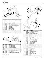
Page 34: ... 160401 HOSE VACUUM 25 W CUFFS 1 6 160430 CUFF HOSE 1 1 2 2 7 160451 CONNECTOR VACUUM HOSE 1 1 2 1 Assembly Included in Assembly FLOOR TOOL 3 1 2 5 4 6 7 8 10 11 9 1213 14 15 16 17 20 21 22 19 23 24 25 18 REF PART DESCRIPTION QTY 600048 FLOOR TOOL COMPLETE 1 1 200403 BK TOOL FLOOR 1 2 200939 SHOES S S FLOOR TOOL 2 3 200927 GRIP ADJUSTABLE COMPLETE 1 4 200912 GRIP FOAM 1 5 140259 SCREW 1 4 20X5 8 1...

Reviews: