background image

186

MM159

Rev. 05 (12–95)

(Operator Manual)

Summary of Contents for 186

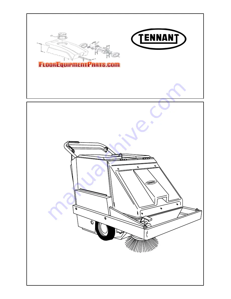
Page 1: ...186 MM159 Rev 05 12 95 Operator Manual ...

Page 2: ...y This machine will provide excellent service However the best results will be obtained at minimum costs if The machine is operated with reasonable care The machine is maintained regularly per the maintenance instructions provided The machine is maintained with TENNANT supplied or equivalent parts Parts and supplies may be ordered by phone or mail from any TENNANT parts and service center distribu...

Page 3: ...arks And Open Flame Away From Refueling Area Make Sure All Safety Devices Are In Place And Operate Properly Check Brakes And Steering For Proper Operation 3 When Using Machine Go Slow On Grades And Slippery Surfaces Use Care When Backing Machine 4 Before Leaving Or Servicing Machine Stop On Level Surface Set Parking Brake Turn Off Machine And Remove Key 5 When Servicing Machine Avoid Moving Parts ...

Page 4: ...comes damaged or illegible install a new decal in its place FOR SAFETY LABEL LOCATED ON THE TOP OF THE SOLUTION TANK TOXIC GASES LABEL LOCATED ON THE LEFT SIDE PANEL BACK STRAIN LABEL LOCATED ON THE UNDERSIDE OF THE FILTER ASSEMBLY 03132 FLAMMABLE MATERIALS LABEL LOCATED ON RIGHT SIDE PANEL FLAMMABLE MATERIALS LABEL LOCATED ON RIGHT SIDE PANEL ...

Page 5: ...AND FUSES 2 9 VACUUM SHUT OFF KNOB 2 9 PARKING BRAKE LEVER 2 9 SQUEEGEE LEVER 2 10 SOLUTION LEVER 2 10 SIDE BRUSH ARM 2 10 THERMO SENTRY 2 10 Page MACHINE OPERATION 2 11 NORMAL SWEEPING OPERATION 2 11 PRE START CHECKLIST 2 11 TO START MACHINE 2 11 TO SWEEP 2 12 TO DUMP HOPPER 2 12 POST OPERATION CHECKLIST ENGINE OPERATING 2 12 TO STOP MACHINE 2 12 POST OPERATION CHECKLIST ENGINE STOPPED 2 13 NORMA...

Page 6: ...TIC For machines serial number 004369 and above 3 18 Page BELTS AND CHAINS 3 19 PROPELLING BELTS 3 19 TO CHECK AND ADJUST PROPELLING BELTS TENSION 3 19 TO REPLACE PROPELLING BELTS 3 20 SIDE BRUSH BELT 3 21 TO CHECK AND ADJUST SIDE BRUSH BELT TENSION 3 21 TO REPLACE SIDE BRUSH BELT 3 22 SHORT MAIN BRUSH BELT 3 23 TO REPLACE SHORT MAIN BRUSH BELT 3 23 LONG MAIN BRUSH BELT 3 23 TO REPLACE LONG MAIN B...

Page 7: ...ine Sheaves and Cover Group 6 6 Fig 5 Covers Group 6 8 Fig 6 Handle and Battery Group 6 10 Fig 7 Engine and Sheaves Group 6 12 Fig 8 Engine and Fuel Tank Group LPG 6 14 Fig 9 Brush Drive Group 6 16 Fig 10 Wheel Drive Group 6 18 Fig 11 Hopper Group 6 19 Fig 12 Vacuum Fan Group 6 20 Fig 13 Filter and Shaker Motor Group 6 21 Fig 14 Instrument Panel Group 6 22 Fig 15 Instrument Panel Group 6 23 Fig 16...

Page 8: ...Breather and Vent Group 8 7 Fig 6 Flywheel Group 8 8 Fig 7 Electric Start Group 8 9 Fig 8 Governor Group 8 10 Fig 9 Ignition Group 8 11 Fig 10 Carburetor Group Gasoline 8 12 Fig 11 Carburetor Group Gasoline 8 13 Fig 12 Fuel Pump Group 8 14 Fig 13 Fuel Tank Group 8 15 Fig 14 Fuel Pump Group LPG 8 16 Fig 15 Carburetor Group LPG 8 17 CROSS REFERENCE 9 1 PART NUMBER TO PAGE NUMBER CROSS REFERENCE LIST...

Page 9: ...N 1 CONTENTS Page MACHINE SPECIFICATIONS 1 3 POWER TYPE 1 3 POWER TRAIN 1 3 SUSPENSION SYSTEM 1 3 SYSTEM FLUID CAPACITIES 1 3 GENERAL MACHINE DIMENSIONS CAPACITIES 1 3 MACHINE WEIGHTS 1 3 GENERAL MACHINE PERFORMANCE 1 3 MACHINE DIMENSIONS 1 4 ...

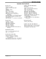
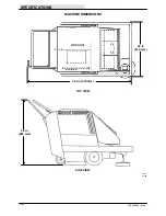
Page 10: ...SPECIFICATIONS 186 MM159 6 94 1Ć2 ...

Page 11: ... SYSTEM Front 10 x 2 00 zero pressure tires 2 Rear 5 x 1 5 caster 1 SYSTEM FLUID CAPACITIES Engine lubricating oil 1 qt 0 95 L Fuel tank 1 25 gal 4 75 L gasoline 20 lb 9 kg LPG Scrub attachment solution tank 14 5 gal 55 L Scrub attachment recovery tank 13 gal 50 L GENERAL MACHINE DIMENSIONS CAPACITIES Length 58 in 1475 mm Width 36 in 915 mm less side brush Height 38 in 965 mm Track front 31 in 790...

Page 12: ...SPECIFICATIONS 186 MM159 6 94 1Ć4 MACHINE DIMENSIONS SIDE VIEW TOP VIEW 36 in 915 mm 58 in 1475 mm 38 in 965 mm 03131 03138 ...

Page 13: ...OPERATION 2 11 NORMAL SWEEPING OPERATION 2 11 PRE START CHECKLIST 2 11 TO START MACHINE 2 11 TO SWEEP 2 12 TO DUMP HOPPER 2 12 POST OPERATION CHECKLIST ENGINE OPERATING 2 12 TO STOP MACHINE 2 12 POST OPERATION CHECKLIST ENGINE STOPPED 2 13 NORMAL SCRUBBING OPERATION 2 13 PRE START CHECKLIST 2 13 TO START MACHINE 2 13 TO SCRUB 2 14 TO DRAIN RECOVERY TANK AND EMPTY DEBRIS TRAY 2 15 POST OPERATION CH...

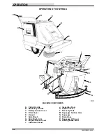
Page 14: ...OPERATION 186 MM159 6 94 2Ć2 ...

Page 15: ...hine FOR SAFETY Do Not Operate Machine Unless Operation Manual Is Read And Understood 3 Check the engine oil level See ENGINE in the MAINTENANCE section 4 Check the main brush adjustment See BRUSHES in the MAINTENANCE section 5 Fill the fuel tank or install an LPG fuel tank on the machine FOR SAFETY When Servicing Machine Keep Flames And Sparks Away From Fuel System Service Area Keep Area Well Ven...

Page 16: ...COMPONENTS A Clutch Handle J Inspection Door B Stationary Handle K Solution Lever C Battery Access Cover L Recovery Tank D Filter Cover M Squeegee Suction Hose E Hopper N Squeegee F Side Brush O Drain Hose G Side Brush Arm P Squeegee Lift Lever H Engine Access Cover Q Parking Brake Lever I Instrument Panel ...

Page 17: ...OLS The symbols are used to identify controls and displays on the machine Filter Shaker Main Brush Free Float Main Brush Down Main Brush Up Vacuum Shut Off Circuit Breaker No 1 Circuit Breaker No 2 Choke Engine Start Key Switch Parking Brake Side Brush ...

Page 18: ...NTS For machines below serial number 006000 A Stationary Handle G Start Switch B Filter Shaker Switch H Clutch Handle C Filter Shaker By pass Switch I Key Operated On Off Switch D Ammeter J Engine Choke Knob E Main Brush Lever K Circuit Breakers F Hour Meter L Vacuum Shut Off Knob ...

Page 19: ...TS For machines serial number 006000 and above A Stationary Handle G Clutch Handle B Filter Shaker By Pass Switch H Clutch Reverse Handle C Ammeter I Key Operated On Off Switch D Main Brush Lever J Engine Choke Knob E Hour Meter K Circuit Breakers F Start Switch L Vacuum Shut Off Knob ...

Page 20: ...the machine is turned off When the switch is in the off position the filter shaker motor will not shake the dust from the filter when the machine is turned off The switch should be in the off position when servicing the machine or when using the scrubber attachment AMMETER The ammeter registers the charging current which is being passed to the battery by the alternator It also registers a discharg...

Page 21: ...e circuit breakers are located on the instrument panel The following chart shows the various circuit breakers and the electrical components they protect PROTECTIVE DEVICE RATING CIRCUIT PROTECTED CB 1 15 A Shaker Motor CB 2 15 A Hour Meter Thermo Sentry Alternator VACUUM SHUT OFF KNOB The vacuum shut off knob is present on machines with the filter bypass option vacuum wand option or the water pick...

Page 22: ...DE BRUSH ARM The side brush arm controls the position of the side brush To raise the side brush pull the lift arm up and push it back into the raised position To lower the side brush pull the arm forward and release it into the down position When parking the machine always raise the brush to prevent the brush bristles from taking a set A 03135 RAISING SIDE BRUSH ARM A Side Brush Arm THERMO SENTRY ...

Page 23: ... proper operation Check service records to determine service requirements TO START MACHINE NOTE Before starting machine perform the pre start checks 1 LPG powered machines Slowly open the liquid service valve NOTE Opening the service valve too quickly may cause the service valve check valve to stop the flow of LPG fuel If the check valve stops the flow of fuel close the valve wait a few seconds an...

Page 24: ...serial number 004369 and above the filter shaker by pass switch must be in the on position to shake the dust filter when the engine is turned off 4 Slowly drive the machine up to the dump site or dumpster Stop the engine 5 Park on level surface FOR SAFETY Before Leaving Or Servicing Machine Stop On Level Surface Set Parking Brake And Turn Off Machine 6 Lift the filter cover 7 Swing the dump lever ...

Page 25: ... for leak spots Check engine lubricating oil level Check fuel level Check for LPG odor or frosting on hoses or components indicating LPG fuel leak Check brakes and controls for proper operation Check service records to determine service requirements TO START MACHINE NOTE Before starting machine perform the pre start checks 1 LPG powered machines Slowly open the liquid service valve NOTE Opening th...

Page 26: ...on put down by the machine For best scrubbing results reduce speed to one half maximum machine speed Shut off solution flow to floor 5 ft 1 5 m before making turns Always raise the rear squeegee before backing machine Adjust solution flow to floor with solution flow control lever to match floor conditions 1 Stop the engine before filling solution tanks FOR SAFETY Before Leaving Or Servicing Machin...

Page 27: ...rom shaking 2 Remove the recovery tank drain hose from its retention plug Lower the hose to the floor drain to drain the tank NOTE The tank will not empty with the vacuum fan operating A B C 03148 RECOVERY TANK DRAIN HOSE A Plug B Drain Hose C Access Door 3 Replace the hose on the retention plug after the tank is empty 4 Lift the debris tray handle off its hanger and pull the tray out from under t...

Page 28: ...ses over the area to be cleaned To double scrub make a single pass over the surface being cleaned with the rear squeegee raised Allow the solution to soak on the floor for 15 to 20 minutes Then make a second scrubbing pass in the normal manner with the rear squeegee lowered FOR SAFETY When Using Machine Go Slow On Grades And Slippery Surfaces OPERATION ON GRADES Drive the machine slowly on grades ...

Page 29: ...ACUUM SHUT OFF KNOB A Vacuum Shut Off Knob B Instrument Panel WATER PICKUP OPTION The water pickup option allows a machine without the scrub attachment to pick up water from the floor The kit includes a filter by pass a squeegee and a recovery tank TO OPERATE THE WATER PICKUP OPTION 1 Pull out the vacuum shut off knob 2 Raise the main brush and side brush 3 Lower the squeegee lever into the down p...

Page 30: ...h The main sweeping brush is also exchanged for a scrubbing brush in the conversion Rear squeegee and recovery tank installation are covered in an instruction bulletin Side scrub brush installation is the same as side sweep brush installation as covered in BRUSHES in the MAINTENANCE section Here we will only cover routine solution tank and debris tray installation and removal TO MOUNT SOLUTION TAN...

Page 31: ... Swivel Screw B Cable C Solution Valve Lever 8 Position the spreader tube in the lowered position A B 03160 SPREADER TUBE A Spreader Tube B Lowered Position Slot 9 Lower the filter assembly TO REMOVE SOLUTION TANK AND DEBRIS TRAY 1 Park the machine next to a floor drain Stop the engine and set the machine parking brake FOR SAFETY Before Leaving Or Servicing Machine Stop On Level Surface Set Parkin...

Page 32: ...ed Spreader Tube 5 Disconnect the solution cable on the machine from the from the solution tank cable 6 Slide the debris tray out from under the solution tank 7 Remove the solution tank 8 Slide the debris hopper into place on the machine Be sure the debris hopper hangers engage the mounting pins A B 03159 HOPPER HANGERS A Hanger B Hopper 9 Replace the tank drain plug ...

Page 33: ...squeegee water pickup blade Rear squeegee out of adjustment Adjust rear squeegee Recovery tank inspection cover Adjust cover or replace seal seal broken Vacuum hose clogged Flush vacuum hoses Recovery tank full Drain tank Float stuck shutting off vacuum Clean float and float guide Debris caught on squeegee Remove debris Debris tray full Empty tray Foam filling recovery tank Empty recovery tank cha...

Page 34: ...y Poor scrubbing performance Debris caught on scrub brushes Remove debris Improper detergent or brushes Check with TENNANT used representative for advice Worn scrub brushes Replace scrub brushes Scrub brushes out of adjustment Adjust scrub brushes Debris tray full Empty tray ...

Page 35: ...lts on the wrap around bumper To tie the machine down strap around the bumper at the attachment bolts A 03136 LEFT SIDE TIE DOWN LOCATION A Tie Down When transporting the machine on a trailer or in a truck be sure to engage the machine parking brake if so equipped and block the machine tires to prevent the machine from rolling ...

Page 36: ...able deposits from forming 1 Empty debris hopper 2 Change engine oil 3 Raise the main brush and side brush 4 Park the machine in a cool dry area 5 Stop the engine 6 Drain the fuel tank 7 Start the engine and let it run out of fuel 8 Remove the spark plug and pour 1 oz 30 cc of new engine oil into the cylinder 9 Crank the engine to distribute the oil then replace the spark plug 10 Clean the engine ...

Page 37: ...SCHEMATIC For machines serial number 004369 and above 3 18 Page BELTS AND CHAINS 3 19 PROPELLING BELTS 3 19 TO CHECK AND ADJUST PROPELLING BELTS TENSION 3 19 TO REPLACE PROPELLING BELTS 3 20 SIDE BRUSH BELT 3 21 TO CHECK AND ADJUST SIDE BRUSH BELT TENSION 3 21 TO REPLACE SIDE BRUSH BELT 3 22 SHORT MAIN BRUSH BELT 3 23 TO REPLACE SHORT MAIN BRUSH BELT 3 23 LONG MAIN BRUSH BELT 3 23 TO REPLACE LONG ...

Page 38: ...E REAR SQUEEGEE BLADE 3 38 TO ADJUST SQUEEGEE 3 39 SCRUB ATTACHMENT 3 41 SCRUB ATTACHMENT 3 41 SOLUTION TANK 3 41 SOLUTION DISTRIBUTION SYSTEM 3 41 DEBRIS TRAY 3 42 TO CHECK AND ADJUST DEBRIS TRAY FLOOR CLEARANCE 3 42 SCRUB BRUSHES 3 42 RECOVERY TANK 3 43 TO DRAIN RECOVERY TANK 3 43 REAR SQUEEGEE 3 43 TO REMOVE SQUEEGEE ASSEMBLY 3 43 TO INSTALL SQUEEGEE ASSEMBLY 3 44 TO REPLACE FRONT SQUEEGEE BLAD...

Page 39: ...INSPECTION After the first 25 hours of operation the following procedures are recommended 1 Check the brush pattern for correct brush adjustment 2 Check the floor skirts to floor clearance 3 Check the side brush and main brush patterns 4 Check the drive chain tension ...

Page 40: ... clearance 5 3 Main brush Check for damage wear and floor clearance 1 8 Side brush Check for damage and wear 1 7 Hopper Check for hopper door seal damage and wear 3 13 Scrub attachment Check scrub brushes for damage and wear 2 Check rear squeegee for damage wear and adjustment 1 25 Hours 12 Engine Change oil EO 1 Clean cooling fins 1 Clean and oil air filter pre cleaner element 1 13 Scrub attachme...

Page 41: ...es pattern 2 7 Hopper Check floor clearance 1 100 Hours 12 Engine Clean or replace and gap spark plug 1 Clean or replace filter element 1 5 Drive chains Check and adjust tension 2 Lubricate SO 2 7 Hopper Clean inside 1 Check floor clearance 1 11 Self adjusting sheave Lubricate EO 1 6 Dust filter Clean or replace 1 17 Differential Lubricate SPL 1 400 Hours 12 Engine Check valve clearance 1 Check br...

Page 42: ...rive Sheave DIFFERENTIAL The differential drives the front wheels The differential has one grease fitting located on the drive shaft inside the drive sheave Lubricate the differential every 100 hours of operation with Lubriplate EMB grease TENNANT Part No 01433 1 BRUSH ARM PIVOTS The brush arm pivots on a stub shaft on each side of the machine Each of the stub shafts are fitted with a grease fitti...

Page 43: ...hub and the caster fork The caster swivel is full when grease appears through the swivel o ring C B A 03143 REAR CASTER A Rear Caster B Axle Grease Fitting C Swivel Grease Fitting SELF ADJUSTING SHEAVE The self adjusting sheave transfers power from the short main brush belt to the main brush Lubricate the sheave shaft with SAE 30 weight engine oil after every 100 hours of operation Avoid getting o...

Page 44: ...irt will wear out a set of piston rings in just a few hours Operating with a clogged air filter element also causes the fuel mixture to be richer which can lead to formation of harmful sludge deposits in the engine Always cover the air intake when the air cleaner is removed for servicing Do not neglect servicing the air cleaner Use only correct parts for replacement Keep all other air intake compo...

Page 45: ...el adjusting needle out counterclockwise to a minimum of one and three quarters turns to a maximum of two turns open Final adjustment is made with the engine running and warm The carburetor should be adjusted with the fuel tank approximately one half full and with the engine running at approximately 800 RPM Turn the main fuel adjusting needle valve out until the engine begins to lose speed rich No...

Page 46: ...eaks and broken protecting rings whenever the tanks are refilled All tank valves must be inspected for leaks using a soap solution Valves must also be checked for dirt paint or other debris in the valve openings The following specific checks must also be made Filler Valve Check for proper functioning and the presence of the handwheel Valve must be closed except during filling Vapor and Liquid Serv...

Page 47: ...he operator should notify the appropriate personnel for appropriate action TO CHANGE AN LPG FUEL TANK 1 Park the machine in a designated safe area FOR SAFETY When Servicing Machine Keep Flames And Sparks Away From Fuel System Service Area Keep Area Well Ventilated 2 Close the tank service valve 3 Operate the engine until it stops from lack of fuel FOR SAFETY Before Leaving Or Servicing Machine Sto...

Page 48: ...an out the bowl when replacing the filter pack REGULATOR The regulator regulates the flow of LPG fuel to the carburetor If any malfunction is noted completely disassemble the regulator Clean all of the parts in alcohol Inspect all of the parts and replace where needed Carefully reassemble the regulator with the seal repair kit Check for proper operation CARBURETOR The carburetor meters fuel to the...

Page 49: ...auge is best for checking the spark plug gap A flat gauge should not be used unless the electrode surfaces have been dressed with a small file to get parallel surfaces between the center and side electrodes Set the spark plug gap by bending the side electrode All spark plugs new or used should have the gaps checked and reset if necessary A B C D 01471 GAPPING THE SPARK PLUG A Spark Plug B Center E...

Page 50: ...SEQUENCE VALVE TAPPET CLEARANCE The valve tappet clearance must be inspected after every 400 hours of operation The intake valve clearance should be 0 006 to 0 008 in 0 15 to 0 20 mm cold The exhaust valve clearance should be 0 017 to 0 019 in 0 43 to 0 48 mm cold Grind off the end of the valve stem to obtain the proper clearance PCV SYSTEM The pcv system including the reed valve and gaskets must ...

Page 51: ... must be checked after every 50 hours of operation It must always be above the battery plates Add distilled water to maintain solution at the correct level above the plates but do not overfill Never add acid to batteries only water Keep vent plugs firmly in place at all times except when adding water or taking hydrometer readings FOR SAFETY When Servicing Machine Avoid Contact With Battery Acid If...

Page 52: ...MAINTENANCE 186 MM159 6 94 3Ć16 ELECTRICAL SCHEMATIC For machines below serial number 003181 03145 ...

Page 53: ...MAINTENANCE 3Ć17 186 MM159 6 94 ELECTRICAL SCHEMATIC For machines serial number 003181 to 004368 03145 ...

Page 54: ...MAINTENANCE 186 MM159 6 94 3Ć18 ELECTRICAL SCHEMATIC For machines serial number 004369 and above 03145 ...

Page 55: ...p 8 if not continue with step 5 to readjust forward belt tension A B C D H G F E I 03151 PROPELLING BELTS A Engine B Clutch Plate C Clutch Plate Bolt D Bolt Slot E Forward Belt Idler Sheave F Reverse Propelling Belt G Forward Propelling Belt H Reverse Belt Idler Sheave I Belt Guide 5 Loosen the forward idler sheave bolt and slide the idler sheave down to tighten the belt this also increases distan...

Page 56: ...om the differential E Tighten the center early style only and left bearing flanges Check for hard rotation of shaft F Tighten the center early style only and left bearing collars G Pull the short differential shaft away from differential to spread the differential gears H Tighten the right side bearing flange Rap on bearing before tightening I Tighten the right bearing collar J Check for free spin...

Page 57: ...very 50 hours of operation TO CHECK AND ADJUST SIDE BRUSH BELT TENSION 1 Stop the engine and set the machine parking brake FOR SAFETY Before Leaving Or Servicing Machine Stop On Level Surface Set Parking Brake And Turn Off Machine 2 Remove the debris hopper 3 Remove the engine access cover right side bumper and cover 4 Place the side brush arm in the down position 5 Check the belt tension at a poi...

Page 58: ...cover and engine access cover 4 Place the side brush arm in the raised position 5 Remove the four speed reducer mounting bolts and the speed reducer from the side brush arm 6 Slide the belt off the engine sheave and out of the machine B A C D 03151 SIDE BRUSH BELT A Engine B Engine Sheave C Side Brush Belt D Belt Guide 7 Position the new belt over the engine sheave under the belt guide and through...

Page 59: ...Evenly tighten the two screws to expand the self adjusting sheave 6 Slip the belt off the sheaves 7 Slide the new belt over the sheaves 8 Unthread the two screws 9 Replace the right side bumper and cover and engine access cover LONG MAIN BRUSH BELT The long main brush belt transfers power from the engine to the main brush two step sheave Check the belt for wear after every 50 hours of operation A ...

Page 60: ...from the two step sheave and slide the sheave off the shaft 11 Pull belt idler back and slide the long main brush belt out of the machine 12 Position the new long main brush belt in the machine 13 Reinstall the two step sheave and reconnect the idler sheave spring 14 Position the side brush belt over the engine sheave and under the belt guide 15 Slide the short main brush belt over the self adjust...

Page 61: ...the drive belt Loosen the top nut to loosen the belt A B C D 03154 VACUUM FAN BELT OLD STYLE A Engine B Adjustment Stud C Vacuum Fan Belt D Jam Nut To adjust belt tension for machines serial number 02253 and above loosen the belt adjusting stud nut Pull the vacuum fan assembly back to tighten the belt and tighten the stud nut A C B 06320 VACUUM FAN NEW STYLE A Vacuum Fan B Adjustment Slot C Stud N...

Page 62: ...ration and then after every 100 hours of operation The wheel drive chains should have 0 5 in 15 mm slack measured midway between the sprockets C B A D 03139 WHEEL DRIVE CHAIN A Adjustment Bolts B Sprocket C Chain D Adjustment Block STATIC DRAG CHAIN A static drag chain is provided to prevent the buildup of static electricity in the machine The chain is attached to the machine by a rear brush skirt...

Page 63: ...of the brush compartment TO INSTALL MAIN BRUSH 1 Slide the main brush through the main brush access door into the brush compartment 2 Rotate the main brush until the slots on the ends of the main brush engage the keys on the main brush drive hub NOTE Do not force the main brush onto the drive hub When the main brush slots and drive hub keys are properly aligned the main brush will easily slip on t...

Page 64: ...e side brush side brush drive hub or shaft The side brush should be replaced when the remaining bristle length measures 1 in 25 mm in length The side brush pattern should be checked after every 50 hours of operation The side brush is properly adjusted when with the side brush arm in the raised position there is approximately 1 in 25 mm of space between the floor and the side brush bristles The sid...

Page 65: ...e parking brake FOR SAFETY Before Leaving Or Servicing Machine Stop On Level Surface Set Parking Brake And Turn Off Machine 2 Pull the side brush arm up into the raised position 3 Remove the side brush retaining bolt or clevis pin 4 Slide the side brush up or down on the shaft until there is approximately 1 in 25 mm of space between the floor and the brush bristles 5 Line up the side brush and dri...

Page 66: ...m Inspect the skirt for wear or damage and proper floor clearance daily A 03157 REAR BRUSH SKIRTS A Rear Brush Skirts HOPPER TOP SEAL The hopper top seal is located on the front edge of the machine frame It seals the area between the top of the hopper and the brush compartment Inspect the seal for wear or damage daily A B 02349 HOPPER TOP SEAL A Seal B Frame MAIN BRUSH COMPARTMENT SKIRTS Two main ...

Page 67: ...th level surface and set the machine parking brake 2 Stop the engine FOR SAFETY Before Leaving Or Servicing Machine Stop On Level Surface Set Parking Brake And Turn Off Machine 3 Empty the debris hopper and replace it on the machine 4 The bottom rear metal edge of the hopper should clear the floor by 0 5 in 15 mm Also be sure the hopper is level side to side 5 To adjust the hopper loosen the hange...

Page 68: ...wn and return to its original position DUST FILTER The dust filter filters the air which is drawn up from the main brush compartment by the vacuum fan It is located inside the dust filter compartment Shake the excess dust from the filter daily and before emptying hopper Inspect and clean or replace the dust filter after every 100 hours of operation To clean the dust filter use one of the following...

Page 69: ...ront filter cover screws and the front filter cover 3 Remove the filter hold down bar Remove the dust filter B A 03158 REMOVING HOLD DOWN BAR A Dust Filter B Hold Down Bar 4 Inspect and clean or replace the dust filter 5 Position the dust filter in the filter frame with the arrows pointing away from the machine 6 Position the filter hold down bar on the filter 7 Secure the front filter cover on th...

Page 70: ...ll TO REPLACE VACUUM WAND BAG 1 Stop the engine and set the machine parking brake FOR SAFETY Before Leaving Or Servicing Machine Stop On Level Surface Set Parking Brake And Turn Off Machine 2 Open the rear access panel 3 Unthread the two vacuum panel thumbscrews Open the panel 4 Pull the bag off the panel connection B A 03156 VACUUM BAG A Vacuum Panel B Bag 5 Position the new bag on the panel Be s...

Page 71: ... tank cleaning job easier It is located on the top of the recovery tank Keep vacuum hoses clean Clogged hoses are a common cause of poor water pickup TO DRAIN RECOVERY TANK 1 Stop the engine and set the machine parking brake FOR SAFETY Before Leaving Or Servicing Machine Stop On Level Surface Set Parking Brake And Turn Off Machine 2 Remove the drain hose from its retention plug A B C D 03148 RECOV...

Page 72: ...dge rotate the top edges down bottom edges up To use the last edge swap the squeegee end for end Replace the back up strips if they become damaged or if they lose their resiliency TO REMOVE SQUEEGEE ASSEMBLY 1 Place the squeegee lever in the up position 2 Stop the engine and set the machine parking brake FOR SAFETY Before Leaving Or Servicing Machine Stop On Level Surface Set Parking Brake And Tur...

Page 73: ...ion 2 Stop the engine and set the machine parking brake FOR SAFETY Before Leaving Or Servicing Machine Stop On Level Surface Set Parking Brake And Turn Off Machine 3 Remove the squeegee assembly from the machine 4 Turn the front squeegee levered cam to the right to relieve tension on the squeegee retention band 5 Remove the stationary cam and levered cam 6 Remove the squeegee retention band 7 Remo...

Page 74: ...parking brake FOR SAFETY Before Leaving Or Servicing Machine Stop On Level Surface Set Parking Brake And Turn Off Machine 3 Remove the squeegee assembly from the machine 4 Turn the rear squeegee levered cam to the right to relieve tension on the squeegee retention band 5 Remove the squeegee retention band stationary cam and levered cam 6 Remove the backup strip and rear squeegee from the squeegee ...

Page 75: ... edge and retighten the levered cam Overtightening the levered cam may damage the squeegee frame and retention band TO ADJUST SQUEEGEE 1 Start the engine 2 Place the squeegee lever in the down position 3 Operate the machine in a forward direction to deflect the squeegee blade 4 Observe the squeegee blade deflection The squeegee blade should be evenly deflected from one end to the other If the sque...

Page 76: ...ct the squeegee blades once again 6 Check the rear squeegee blade deflection The backup strip controls the squeegee blade deflection Flip the backup strip to increase or decrease the squeegee blade deflection A B 03164 BACKUP STRIP A Rear Squeegee Blade B Backup Strip This position has the smallest deflection ...

Page 77: ...mounted in place of the hopper The solution tank requires no regular maintenance If detergent cakes on the bottom of the tank remove the deposits with a strong blast of water A B C 03150 SOLUTION TANK A Solution Tank B Tank Cover C Soap Basket SOLUTION DISTRIBUTION SYSTEM The solution distribution system consists of a feed line from the solution tank to a cable controlled flow rate valve then to t...

Page 78: ...ON TANK HANGER A Solution Tank B Hanger 4 The bottom rear metal edge of the tray should clear the floor by 0 18 in 5 mm Also be sure the tray is level side to side 5 To adjust the tray for old style loosen the caster bracket bolts reposition the caster bracket and retighten the bolts For new style loosen caster bolts reposition the caster and retighten the bolts A B 03161 DEBRIS TRAY CASTER A Debr...

Page 79: ...h the vacuum fan operating 4 Spray the inside of the tank with clean water Remove all sludge and debris from the bottom of the tank NOTE The water must not be hotter than 130 F 54 C or tank damage may occur 5 Return the drain hose to its retention plug REAR SQUEEGEE The rear squeegee channels water into the vacuum fan suction The front squeegee blade channels the water the rear blade wipes the flo...

Page 80: ...he side bolts are above the squeegee frame 4 Slide the squeegee assembly retaining pin through the squeegee pivot pin 5 Push the squeegee suction hose onto the recovery tank connector TO REPLACE FRONT SQUEEGEE BLADE 1 Place the squeegee lever in the up position 2 Stop the engine and set the machine parking brake FOR SAFETY Before Leaving Or Servicing Machine Stop On Level Surface Set Parking Brake...

Page 81: ...ng the levered cam may damage the squeegee frame and retention band 12 Reinstall the squeegee assembly on the machine TO REPLACE REAR SQUEEGEE BLADE 1 Place the squeegee lever into the up position 2 Stop the engine and set the machine parking brake FOR SAFETY Before Leaving Or Servicing Machine Stop On Level Surface Set Parking Brake And Turn Off Machine 3 Remove the squeegee assembly from the mac...

Page 82: ... STATIONARY CAM A Rear Squeegee Blade B Retention Band C Stationary Cam 11 Position the levered cam on the squeegee retention band with the lever down A B C 00933 INSTALLING LEVERED CAM A Rear Squeegee Blade B Levered Cam C Retention Band 12 Pull the levered cam lever up to tighten the rear squeegee in place NOTE The cam lever should be above the horizontal axis to keep from possibly scratching th...

Page 83: ...an the middle of the squeegee turn the squeegee tips adjusting knob to the left Raise and lower the squeegee operate the machine and recheck the squeegee tips deflection if an adjustment was made A B 03166 SQUEEGEE TIPS ADJUSTMENT KNOB A Squeegee Tips Adjustment Knob B Squeegee Assembly 5 Operate the machine in a forward direction with the squeegee down to deflect the squeegee blades once again 6 ...

Page 84: ...MAINTENANCE 186 MM159 6 94 3Ć48 ...

Page 85: ...APPENDIX 4Ć1 186 MM159 6 94 SECTION 4 CONTENTS Page HARDWARE INFORMATION 4 3 STANDARD BOLT TORQUE CHART 4 3 METRIC BOLT TORQUE CHART 4 3 BOLT IDENTIFICATION 4 3 THREAD SEALANT AND LOCKING COMPOUNDS 4 3 ...

Page 86: ...APPENDIX 186 MM159 6 94 4Ć2 ...

Page 87: ...91 380 313 407 424 552 1 00 in 500 650 678 881 757 984 1026 1334 NOTE Decrease torque by 20 when using a thread lubricant METRIC BOLT TORQUE CHART Thread Class 8 8 Class 10 9 Size Torque ft lb Nm Torque ft lb Nm ______________________________________________________________ M4 2 3 3 4 M5 4 5 6 8 M6 7 9 10 14 M8 18 24 25 34 M10 32 43 47 64 M12 58 79 83 112 M14 94 127 133 180 M16 144 195 196 265 M20...

Page 88: ...APPENDIX 186 MM159 6 94 4Ć4 ...

Reviews: