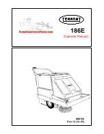
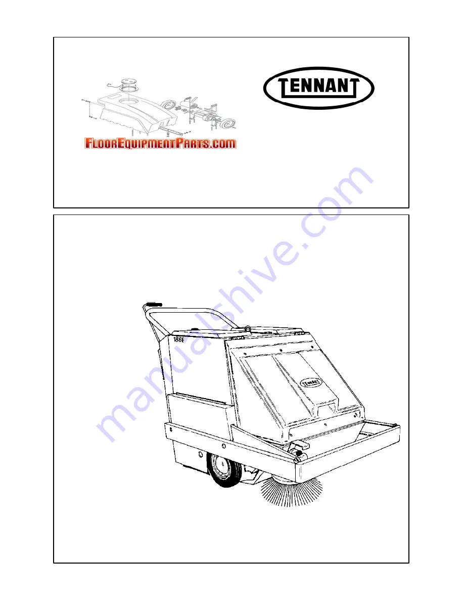
background image

186E

MM160

Rev. 12 (12–95)

(Operator Manual)

Summary of Contents for 186E

Page 1: ...186E MM160 Rev 12 12 95 Operator Manual ...

Page 2: ...de excellent service However the best results will be obtained at minimum costs if The machine is operated with reasonable care The machine is maintained regularly per the maintenance instructions provided The machine is maintained with Tennant Company supplied or equivalent parts Parts and supplies may be ordered by phone or mail from any Tennant Company parts and service center distributor or fr...

Page 3: ...se In Those Areas 2 Before Starting Machine Make Sure All Safety Devices Are In Place And Operate Properly Check Brakes And Steering For Proper Operation 3 When Using Machine Go Slow On Grades And Slippery Surfaces Use Care When Backing Machine 4 Before Leaving Or Servicing Machine Stop On Level Surface Set Parking Brake Turn Off Machine And Remove Key 5 When Servicing Machine Avoid Moving Parts D...

Page 4: ...omes damaged or illegible install a new decal in its place BATTERY CAUTION LABEL LOCATED BETWEEN THE BATTERIES 03167 FOR SAFETY LABEL LOCATED ON THE TOP OF THE SOLUTION TANK FLAMMABLE MATERIALS LABEL LOCATED ON RIGHT SIDE PANEL FLAMMABLE MATERIALS LABEL LOCATED ON RIGHT SIDE PANEL BACK STRAIN LABEL LOCATED ON THE UNDERSIDE OF THE FILTER ASSEMBLY ...

Page 5: ...R TIMER 2 9 CHARGER GAUGE 2 10 VACUUM SHUT OFF KNOB 2 10 CHARGER PANEL 2 10 PARKING BRAKE LEVER 2 10 SQUEEGEE LEVER 2 10 SOLUTION LEVER 2 11 SIDE BRUSH ARM 2 11 THERMO SENTRY 2 11 Page MACHINE OPERATION 2 12 NORMAL SWEEPING OPERATION 2 12 PRE START CHECKLIST 2 12 TO START MACHINE 2 12 TO SWEEP 2 12 TO DUMP HOPPER 2 12 POST OPERATION CHECKLIST MOTOR OPERATING 2 13 TO STOP MACHINE 2 13 POST OPERATIO...

Page 6: ...BRUSH BELT TENSION 3 19 TO REPLACE SIDE BRUSH BELT 3 20 SHORT MAIN BRUSH BELT 3 20 TO REPLACE SHORT MAIN BRUSH BELT 3 20 LONG MAIN BRUSH BELT 3 21 TO REPLACE LONG MAIN BRUSH BELT 3 21 Page VACUUM FAN BELT 3 22 TO CHECK AND ADJUST VACUUM FAN BELT TENSION 3 22 TO REPLACE VACUUM FAN BELT 3 24 WHEEL DRIVE CHAINS 3 24 STATIC DRAG CHAIN 3 24 BRUSHES 3 25 MAIN BRUSH 3 25 TO REMOVE MAIN BRUSH 3 25 TO INST...

Page 7: ... Group 6 19 Fig 14 Label Group 6 20 Fig 15 Label Group 6 21 Fig 16 Wire Harnesses Group 6 22 Fig 17 Wire Harnesses Group 6 24 Fig 18 Wire Harnesses Group 6 26 Page EE PARTS 7 1 Fig 1 Electrical Components Group EE 7 2 Fig 2 Electrical Components Group EE 7 4 Fig 3 Wire Harnesses Group EE 7 6 Fig 4 Wire Harnesses Group EE 7 8 Fig 5 Wire Harnesses Group EE 7 10 Fig 6 Cover Retainer Group EE 7 12 OPT...

Page 8: ...GENERAL INFORMATION 186E MM160 6 94 vi ...

Page 9: ...N 1 CONTENTS Page MACHINE SPECIFICATIONS 1 3 POWER TYPE 1 3 POWER TRAIN 1 3 SUSPENSION SYSTEM 1 3 SYSTEM FLUID CAPACITIES 1 3 GENERAL MACHINE DIMENSIONS CAPACITIES 1 3 MACHINE WEIGHTS 1 3 GENERAL MACHINE PERFORMANCE 1 3 MACHINE DIMENSIONS 1 4 ...

Page 10: ...SPECIFICATIONS 186E MM160 6 94 1Ć2 ...

Page 11: ... pressure tires 2 Rear 5 x 1 5 caster 1 SYSTEM FLUID CAPACITIES Scrub attachment solution tank 14 5 gal 55 L Scrub attachment recovery tank 13 gal 50 L GENERAL MACHINE DIMENSIONS CAPACITIES Length 58 in 1475 mm Width 36 in 915 mm less side brush Height 38 in 965 mm Track front 31 in 790 mm Wheel base 23 5 in 595 mm Main brush width 26 in 660 mm Main brush diameter 10 in 255 mm Side brush diameter ...

Page 12: ...SPECIFICATIONS 186E MM160 6 94 1Ć4 MACHINE DIMENSIONS SIDE VIEW TOP VIEW 36 in 915 mm 58 in 1475 mm 38 in 965 mm 03131 ...

Page 13: ...H ARM 2 11 THERMO SENTRY 2 11 MACHINE OPERATION 2 12 NORMAL SWEEPING OPERATION 2 12 PRE START CHECKLIST 2 12 TO START MACHINE 2 12 TO SWEEP 2 12 TO DUMP HOPPER 2 12 POST OPERATION CHECKLIST MOTOR OPERATING 2 13 TO STOP MACHINE 2 13 POST OPERATION CHECKLIST MOTOR STOPPED 2 13 Page NORMAL SCRUBBING OPERATION 2 13 PRE START CHECKLIST 2 13 TO START MACHINE 2 14 TO SCRUB 2 14 TO DRAIN RECOVERY TANK AND...

Page 14: ...OPERATION 186E MM160 6 94 2Ć2 ...

Page 15: ...tivate them as described in ACTIVATING DRY TYPE BATTERIES in the MAINTENANCE section A B 00879 CHECKING BATTERY ELECTROLYTE LEVEL A Battery B Electrolyte Indicator Ring FOR SAFETY When Servicing Machine Avoid Contact With Battery Acid 4 Check the battery specific gravity to determine the state of charge as described in BATTERIES in the MAINTENANCE section Charge the batteries if necessary 5 Connec...

Page 16: ...E COMPONENTS A Clutch Handle J Inspection Door B Stationary Handle K Solution Lever C Left Access Cover L Recovery Tank D Filter Cover M Squeegee Suction Hose E Hopper N Squeegee F Side Brush O Drain Hose G Side Brush Arm P Squeegee Lift Lever H Right Access Cover Q Parking Brake Lever I Instrument Panel ...

Page 17: ... controls and displays on the machine Filter Shaker Circuit Breaker No 3 Fan Main Brush Free Float Main Brush Down Main Brush Up Circuit Breaker No 1 Circuit Breaker No 2 Vacuum Shut Off Key Switch Parking Brake Side Brush Interrupt Switch Battery Charger Interrupt Battery Charger Battery ...

Page 18: ...ines below serial number 006000 A Stationary Handle H Clutch Handle B Filter Shaker Switch I Circuit Breakers C Filter Shaker By Pass Switch J Vacuum Fan Switch D Battery Condition Gauge K Charger Timer E Main Brush Lever L Charger Gauge F Hour Meter M Vacuum Shut Off Knob G Key Operated On Off Switch ...

Page 19: ...8 CONTROLS AND INSTRUMENTS For machines serial number 006000 and above A Stationary Handle H Clutch Reverse Handle B Filter Shaker By Pass Switch I Circuit Breakers C Battery Condition Gauge Voltmeter J Vacuum Fan Switch D Main Brush Lever K Charger Timer E Hour Meter L Charger Gauge F Key Operated On Off Switch M Vacuum Shut Off Knob G Clutch Handle N Charger Panel ...

Page 20: ...ilter shaker When the switch is in the on position the filter shaker motor will shake the dust from the filter for 20 seconds when the machine is turned off When the switch is in the off position the filter shaker motor will not shake the dust from the filter when the machine is turned off The switch should be in the off position when servicing the machine or when using the scrubber attachment BAT...

Page 21: ...S Circuit breakers are resetable circuit protection devices designed to stop the flow of current in the event of a circuit overload Once tripped circuit breakers must be manually reset by pressing the circuit breaker button in If the overload which caused the circuit breaker to trip is still present in the circuit the circuit breaker will continue to stop current flow until the overload is correct...

Page 22: ...ch while unplugging the charger A 06898 CHARGER PANEL A Interrupt Switch PARKING BRAKE LEVER The parking brake lever controls the brake on the front wheel To set the parking brake for machines below serial numbers 002316 pull the handle back To release the parking brake pull the quick release notch To set the parking brake for machines serial number 002316 to 005999 pull the handle up and over the...

Page 23: ...the raised position To lower the side brush pull the arm forward and release it into the down position When parking the machine always raise the brush to prevent the brush bristles from taking a set A 03135 RAISING SIDE BRUSH ARM A Side Brush Arm THERMO SENTRY The Thermo Sentry is a thermostat that senses the temperature of the air drawn into the vacuum fan from the hopper The thermostat controls ...

Page 24: ...ine to the area to be swept TO SWEEP Plan the sweeping in advance Try to arrange long runs with minimum stopping and starting Sweep debris from very narrow aisles into main aisles ahead of time Do an entire floor or section at one time Pick up oversize debris before sweeping Flatten or remove bulky cartons from aisles before sweeping Pick up pieces of wire twine string etc which could become entan...

Page 25: ...ire or string tangled on brushes Check for leaks NORMAL SCRUBBING OPERATION A normal scrubbing operation consists of seven typical operations pre start checklist starting machine scrubbing draining recovery tank and emptying debris tray post operation checklist motor operating stopping machine and post operation checklist motor stopped PRE START CHECKLIST lists things to check before starting the ...

Page 26: ...ns consult the local Tennant Company Representative WARNING Flammable Materials Can Cause An Explosion Or Fire Do Not Use Flammable Materials In Tank s The recovery tank should be drained after the solution tank is empty and whenever the float rises and stops water vacuum The recovery tank may fill before the solution tank empties if standing water is picked up in addition to the solution put down...

Page 27: ...ry tank float stops vacuum return to the solution dump filling site Drain the recovery tank empty the debris tray and refill the solution tank WARNING Flammable Materials Or Reactive Metals Can Cause Explosion Or Fire Do Not Pick Up TO DRAIN RECOVERY TANK AND EMPTY DEBRIS TRAY 1 Park the machine next to a floor drain Turn off the machine and vacuum fan switch Set the machine parking brake FOR SAFE...

Page 28: ...topping the machine 2 Lift the squeegee lever into the up position 3 Place the solution spreader tube in the up position 4 Pull the side brush arm into the raised position 5 Turn the on off switch key to the left Remove the key from the on off switch FOR SAFETY Before Leaving Or Servicing Machine Stop On Level Surface Set Parking Brake And Turn Off Machine And Remove Key NOTE For machines serial n...

Page 29: ... Machine Go Slow On Grades And Slippery Surfaces VACUUM WAND OPTION The vacuum wand option gives the machine the added flexibility of picking up debris not accessible to the machine An 84 in 2135 mm hose utilizes the machine vacuum system TO OPERATE VACUUM WAND 1 Stop the machine close to the area to be cleaned 2 Raise the main brush and side brush 3 Turn off the machine and set the machine parkin...

Page 30: ...e on the retention plug after the tank is empty NOTE The tank will not empty with the vacuum fan operating A B 03148 RECOVERY TANK DRAIN HOSE A Plug B Drain Hose SCRUB ATTACHMENT The scrub attachment option gives the machine the added flexibility to scrub floors It consists of five groups of parts the solution tank and debris tray the side and main scrub brushes the recovery tank the vacuum fan an...

Page 31: ...der the solution tank A B 03149 DEBRIS TRAY A Debris Tray B Handle Hanger 6 Place the tray handle on its hanger 7 Connect the solution cable on the tank to the cable on the machine Do not twist the cable A B 03137 CONNECTING SOLUTION CABLE A Tank Cable B Machine Cable NOTE If twisting is required to connect the cables loosen the valve swivel screw and allow the cable to relax Connect the cables an...

Page 32: ...he filter shaker by pass switch should be in the off position to prevent the filter shaker from shaking 2 Raise the filter assembly 3 Position the spreader tube in the raised position 4 Remove the plug on the bottom of the solution tank to drain the solution tank A B C 03160 DRAIN PLUG A Drain Plug B Solution Tank C Raised Spreader Tube 5 Disconnect the solution cable on the machine from the solut...

Page 33: ...pickup Rear squeegee out of adjustment Adjust rear squeegee Recovery tank inspection cover Adjust cover or replace seal seal broken Vacuum hose clogged Flush vacuum hoses Fan filter clogged Clean or replace filter Recovery tank full Drain tank Float stuck shutting off vacuum Clean float and float guide Debris caught on squeegee Remove debris Debris tray full Empty tray Foam filling recovery tank E...

Page 34: ...y Poor scrubbing performance Debris caught on scrub brushes Remove debris Improper detergent or Check with TENNANT brushes used representative for advice Worn scrub brushes Replace scrub brushes Scrub brushes out of adjustment Adjust scrub brushes Debris tray full Empty tray ...

Page 35: ...e wrap around bumper To tie the machine down strap around the bumper at the attachment bolts A 03136 LEFT SIDE TIE DOWN LOCATION A Tie Down Location When transporting the machine on a trailer or in a truck be sure to engage the machine parking brake if so equipped and block the machine tires to prevent the machine from rolling ...

Page 36: ...ods of time the following procedures must be followed to lessen the chance of rust sludge or other undesirable deposits from forming 1 Empty debris hopper 2 Raise the main brush and side brush 3 Fully charge the batteries 4 Disconnect the batteries to machine connector 5 Park the machine in a cool dry area ...

Page 37: ...USH BELT TENSION 3 19 TO REPLACE SIDE BRUSH BELT 3 20 SHORT MAIN BRUSH BELT 3 20 TO REPLACE SHORT MAIN BRUSH BELT 3 20 LONG MAIN BRUSH BELT 3 21 TO REPLACE LONG MAIN BRUSH BELT 3 21 Page VACUUM FAN BELT 3 22 TO CHECK AND ADJUST VACUUM FAN BELT TENSION 3 22 TO REPLACE VACUUM FAN BELT 3 24 WHEEL DRIVE CHAINS 3 24 STATIC DRAG CHAIN 3 24 BRUSHES 3 25 MAIN BRUSH 3 25 TO REMOVE MAIN BRUSH 3 25 TO INSTAL...

Page 38: ... DEBRIS TRAY 3 40 TO CHECK AND ADJUST DEBRIS TRAY FLOOR CLEARANCE 3 40 SCRUB BRUSHES 3 40 RECOVERY TANK 3 41 TO DRAIN RECOVERY TANK 3 41 VACUUM FAN 3 41 REAR SQUEEGEE 3 42 TO REMOVE SQUEEGEE ASSEMBLY 3 42 TO INSTALL SQUEEGEE ASSEMBLY 3 43 TO REPLACE FRONT SQUEEGEE BLADE 3 43 TO REPLACE REAR SQUEEGEE BLADE 3 44 TO ADJUST SQUEEGEE 3 46 ...

Page 39: ...INSPECTION After the first 25 hours of operation the following procedures are recommended 1 Check the brush pattern for correct brush adjustment 2 Check the floor skirts to floor clearance 3 Check the side brush and main brush patterns 4 Check the drive chain tension ...

Page 40: ... and floor clearance 1 8 Side brush Check for damage and wear 1 7 Hopper Check for hopper door seal damage and wear 3 Scrub attachment Check rear squeegee for damage wear and adjustment 1 Check scrub brushes for damage and wear 2 25 Hours 12 Scrub attachment Clean recovery tank 1 Check squeegee for damage wear and adjustment 1 Clean vacuum fan filter 1 Vacuum wand attachment Clean vacuum fan filte...

Page 41: ...bris tray floor clearance 1 Check scrub brush pattern 2 7 Hopper Check floor clearance 1 100 Hours 5 Drive chains Check and adjust tension 2 Lubricate SO 2 7 Hopper Clean inside 1 Check floor clearance 1 6 Dust filter Clean or replace 1 11 Self adjusting sheave Lubricate EO 1 1 Batteries Clean top surface and terminals DW 2 17 Differential Lubricate SPL 1 400 Hours 15 Propelling motor Blow out dus...

Page 42: ... operation with Lubriplate EMB grease TENNANT Part No 01433 1 BRUSH ARM PIVOTS The brush arm pivots on a stub shaft on each side of the machine Each of the stub shafts are fitted with a grease fitting Apply Lubriplate EMB grease TENNANT Part No 01433 1 to the grease fittings after every 50 hours of operation A 02341 LEFT SIDE BRUSH ARM PIVOT GREASE FITTING A Grease Fitting SIDE BRUSH GEAR BOX The ...

Page 43: ... hub and the caster fork The caster swivel is full when grease appears through the swivel o ring C B A 03143 REAR CASTER A Rear Caster B Axle Grease Fitting C Swivel Grease Fitting SELF ADJUSTING SHEAVE The self adjusting sheave transfers power from the short main brush belt to the main brush Lubricate the sheave shaft with SAE 30 weight engine oil after every 100 hours of operation Avoid getting ...

Page 44: ...eration The electrolyte level must always be above the battery plates Add distilled water to maintain solution at the correct level above the plates but do not overfill Never add acid to batteries only water Keep vent plugs firmly in place at all times except when adding water or taking hydrometer readings FOR SAFETY When Servicing Machine Avoid Contact With Battery Acid Use a hydrometer to check ...

Page 45: ...es Emit Hydrogen Gas Explosion Or Fire Can Result Keep Sparks And Open Flame Away Keep Covers Open When Charging 4 Check the electrolyte level in the batteries Before charging add just enough distilled water to cover the plates Then after charging is completed add enough water to bring the electrolyte up to the indicator mark If the water level is topped off before charging normal expansion of the...

Page 46: ... On Indicator Lamp D Red Incomplete Battery Status Indicator Lamp E Yellow 80 Charge Indicator Lamp F Green Complete Charge Indicator Lamp NOTE If the red no charge indicator lamp lights when the charger is plugged into a wall outlet the charger can not charge the battery meaning there is something wrong with the battery When the lamps stop flashing the red incomplete battery status indicator lamp...

Page 47: ... mm above the battery plates 5 Check the specific gravity of the batteries Charge the batteries until the specific gravity is 1 260 to 1 280 6 Add battery acid if necessary to 0 38 in 10 mm above the battery plates 7 Insert battery vent caps in the vent holes 8 Clean the battery posts and cables 9 Install the batteries in the machine 10 Connect the battery cables to the batteries See the STANDARD ...

Page 48: ...MAINTENANCE 186E MM160 6 94 3Ć12 ELECTRICAL SCHEMATIC 186E For machines below serial number 004369 03130 ...

Page 49: ...MAINTENANCE 3Ć13 186E MM160 6 94 ELECTRICAL SCHEMATIC 186E For machines serial number 004369 to 006822 03130 ...

Page 50: ...MAINTENANCE 186E MM160 6 94 3Ć14 ELECTRICAL SCHEMATIC 186E For machines serial number 006823 and above 03130 ...

Page 51: ...MAINTENANCE 3Ć15 186E MM160 6 94 ELECTRICAL SCHEMATIC 186EE For machines below serial number 006823 03095 ...

Page 52: ...MAINTENANCE 186E MM160 6 94 3Ć16 ELECTRICAL SCHEMATIC 186EE For machines serial number 006823 and above 03095 ...

Page 53: ...olt It should not touch the end of the slot If the handle and bolt are in the proper position skip to step 8 if not continue with step 5 to readjust forward belt tension A B C D H G F E I 03151 PROPELLING BELTS A Motor B Clutch Plate C Clutch Plate Bolt D Bolt Slot E Forward Belt Idler Sheave F Reverse Propelling Belt G Forward Propelling Belt H Reverse Belt Idler Sheave I Belt Guide 5 Loosen the ...

Page 54: ...l the shaft away from the differential E Tighten the center early style only and left bearing flanges Check for hard rotation of shaft F Tighten the center early style only and left bearing collars G Pull the short differential shaft away from differential to spread the differential gears H Tighten the right side bearing flange Rap on bearing before tightening I Tighten the right bearing collar J ...

Page 55: ...efore Leaving Or Servicing Machine Stop On Level Surface Set Parking Brake And Turn Off Machine 2 Lift the filter cover 3 Remove the debris hopper 4 Remove the access cover and right side bumper and cover 5 Place the side brush arm in the down position 6 Check the belt tension at a point 9 in 230 mm from the motor shaft The belt should deflect 0 75 in 20 mm from a force of 6 lb 3 kg B A 03151 SIDE...

Page 56: ...elt guide and through the side brush arm 8 Loop the belt over the speed reducer sheave and bolt the speed reducer back onto the side brush arm 9 Adjust the belt tension as described in TO CHECK AND ADJUST SIDE BRUSH BELT TENSION 10 Replace the right side bumper and cover and access cover 11 Replace the debris hopper SHORT MAIN BRUSH BELT The short main brush belt transfers power from the main brus...

Page 57: ...t transfers power from the motor to the main brush two step sheave Check the belt for wear after every 50 hours of operation A belt idler is provided to control belt tension and is not adjustable TO REPLACE LONG MAIN BRUSH BELT 1 Turn off the machine and set the machine parking brake FOR SAFETY Before Leaving Or Servicing Machine Stop On Level Surface Set Parking Brake And Turn Off Machine 2 Remov...

Page 58: ...pring 14 Position the side brush belt over the motor sheave and under the belt guide 15 Slide the short main brush belt over the self adjusting sheave and the two step sheave 16 Unthread the two screws separating the self adjusting sheave 17 Adjust the belt tension as described in TO CHECK AND ADJUST SIDE BRUSH BELT TENSION 18 Replace the right side bumper and cover and access cover 19 Replace the...

Page 59: ...B A D C 03155 VACUUM FAN BELT OLD STYLE A Motor B Adjustment Stud C Vacuum Fan Belt D Jam Nut To adjust belt tension on machines with serial numbers 02253 and above loosen the belt adjusting stud nut Pull the vacuum fan assembly back to tighten the belt and tighten the stud nut A C B 06320 VACUUM FAN NEW STYLE A Vacuum Fan B Adjustment Slot C Stud Nut 5 Tighten all nuts and recheck belt tension 6 ...

Page 60: ...sfer power from the differential to the drive wheels Lubricate the chains with a penetrating type spray lubricant after every 100 hours of operation Check the chains for wear or damage and tension after the first 50 hours of operation and then after every 100 hours of operation The wheel drive chains should have 0 5 in 15 mm slack measured midway between the sprockets C B A D 03139 WHEEL DRIVE CHA...

Page 61: ...h out of the brush compartment TO INSTALL MAIN BRUSH 1 Slide the main brush through the main brush access door into the brush compartment 2 Rotate the main brush until the slots on the ends of the main brush engage the keys on the main brush drive hub NOTE Do not force the main brush onto the drive hub When the main brush slots and drive hub keys are properly aligned the main brush will easily eng...

Page 62: ...h drive hub or shaft The side brush should be replaced when the remaining bristle length measures 1 in 25 mm in length The side brush pattern should be checked after every 50 hours of operation The side brush is properly adjusted when with the side brush arm in the raised position there is approximately 1 in 25 mm of space between the floor and the side brush bristles Side brush adjustments are ma...

Page 63: ...hine parking brake FOR SAFETY Before Leaving Or Servicing Machine Stop On Level Surface Set Parking Brake And Turn Off Machine 2 Pull the side brush arm up into the raised position 3 Remove the side brush retaining bolt or clevis pin 4 Slide the side brush up or down on the shaft until there is approximately 1 in 25 mm of space between the floor and the brush bristles 5 Line up the side brush and ...

Page 64: ...mm Inspect the skirt for wear or damage and proper floor clearance daily A 03157 REAR BRUSH SKIRTS A Rear Brush Skirts HOPPER TOP SEAL The hopper top seal is located on the front edge of the machine frame It seals the area between the top of the hopper and the brush compartment Inspect the seal for wear or damage daily A B 02349 HOPPER TOP SEAL A Seal B Frame MAIN BRUSH COMPARTMENT SKIRTS Two main...

Page 65: ... level surface 2 Turn off the machine and set the machine parking brake FOR SAFETY Before Leaving Or Servicing Machine Stop On Level Surface Set Parking Brake And Turn Off Machine 3 Empty the debris hopper and replace it on the machine 4 The bottom rear metal edge of the hopper should clear the floor by 0 5 in 15 mm Also be sure the hopper is level side to side 5 To adjust the hopper loosen the ha...

Page 66: ...l not float Push the hopper down to check it should be able to go down and return to its original position DUST FILTER The dust filter filters the air which is drawn up from the main brush compartment by the vacuum fan It is located inside the dust filter compartment Shake the excess dust from the filter daily and before emptying hopper Inspect and clean or replace the dust filter after every 100 ...

Page 67: ...e six front filter cover screws and the front filter cover 3 Remove the filter hold down bar Remove the dust filter B A 03158 REMOVING HOLD DOWN BAR A Dust Filter B Hold Down Bar 4 Inspect and clean or replace the dust filter 5 Position the dust filter in the filter frame with the arrows pointing away from the machine 6 Position the filter hold down bar on the filter 7 Secure the front filter cove...

Page 68: ...nel 3 Unthread the two vacuum panel thumbscrews Open the panel 4 Pull the bag off the panel connection B A 03156 VACUUM BAG A Vacuum Panel B Bag 5 Position the new bag on the panel Be sure the bag is not pinched when closing the door 6 Close and secure the panel with the thumbscrews 7 Close the rear access panel TO CLEAN VACUUM FAN FILTER 1 Turn off the machine and set the machine parking brake FO...

Page 69: ... D Cover RECOVERY TANK The recovery tank stores the water solution picked up by the machine squeegee and vacuum fan The recovery tank is located at the rear of the machine The recovery tank should be drained after the solution tank is empty or whenever the float rises and stops the water vacuum Clean the recovery tank after every work shift An inspection door has been provided to make the tank cle...

Page 70: ... blade The rear blade has four wiping edges To use them all start with one wiping edge To use the next wiping edge swap the squeegee end for end To use the next wiping edge rotate the top edges down bottom edges up To use the last edge swap the squeegee end for end Replace the back up strips if they become damaged or if they lose their resiliency TO REMOVE SQUEEGEE ASSEMBLY 1 Place the squeegee le...

Page 71: ...ion 2 Turn off the machine and set the machine parking brake FOR SAFETY Before Leaving Or Servicing Machine Stop On Level Surface Set Parking Brake And Turn Off Machine 3 Remove the squeegee assembly from the machine 4 Turn the front squeegee levered cam to the right to relieve tension on the squeegee retention band 5 Remove the stationary cam and levered cam 6 Remove the squeegee retention band 7...

Page 72: ...ne parking brake FOR SAFETY Before Leaving Or Servicing Machine Stop On Level Surface Set Parking Brake And Turn Off Machine 3 Remove the squeegee assembly from the machine 4 Turn the rear squeegee levered cam to the right to relieve tension on the squeegee retention band 5 Remove the squeegee retention band stationary cam and levered cam 6 Remove the backup strip and rear squeegee from the squeeg...

Page 73: ...levered cam may damage the squeegee frame and retention band TO ADJUST SQUEEGEE 1 Start the motor 2 Place the squeegee lever in the down position 3 Operate the machine in a forward direction to deflect the squeegee blade 4 Observe the squeegee blade deflection The squeegee blade should be evenly deflected from one end to the other If the squeegee tips are deflecting less than the middle of the squ...

Page 74: ...egee blade deflection The backup strip controls the squeegee blade deflection Flip the backup strip to increase or decrease the squeegee blade deflection A B 03164 BACKUP STRIP A Rear Squeegee Blade B Backup Strip This position has the smallest deflection ...

Page 75: ...rgent solution It is mounted in place of the hopper The solution tank requires no regular maintenance If detergent cakes on the bottom of the tank remove the deposits with a strong blast of water A B C 03150 SOLUTION TANK A Solution Tank B Tank Cover C Soap Basket SOLUTION DISTRIBUTION SYSTEM The solution distribution system consists of a feed line from the solution tank to a cable controlled flow...

Page 76: ...LUTION TANK HANGER A Solution Tank B Hanger 5 The bottom rear metal edge of the tray should clear the floor by 0 18 in 5 mm Also be sure the tray is level side to side 6 To adjust the tray for old style loosen the caster bracket bolts reposition the caster bracket and retighten the bolts For new style loosen caster bolts reposition the caster and retighten the bolts A B 03161 DEBRIS TRAY CASTER A ...

Page 77: ...d Turn Off Machine 2 Remove the drain hose from its retention plug A B C D 03148 RECOVERY TANK DRAIN HOSE A Retention Plug B Drain Hose C Recovery Tank D Inspection Door 3 Lower the hose to a floor drain to drain the tank NOTE The tank will not empty with the vacuum fan operating 4 Spray the inside of the tank with clean water Remove all sludge and debris from the bottom of the tank NOTE The water...

Page 78: ...dge rotate the top edges down bottom edges up To use the last edge swap the squeegee end for end Replace the back up strips if they become damaged or if they lose their resiliency TO REMOVE SQUEEGEE ASSEMBLY 1 Place the squeegee lever in the up position 2 Turn off the machine and set the machine parking brake FOR SAFETY Before Leaving Or Servicing Machine Stop On Level Surface Set Parking Brake An...

Page 79: ...ion 2 Turn off the machine and set the machine parking brake FOR SAFETY Before Leaving Or Servicing Machine Stop On Level Surface Set Parking Brake And Turn Off Machine 3 Remove the squeegee assembly from the machine 4 Turn the front squeegee levered cam to the right to relieve tension on the squeegee retention band 5 Remove the stationary cam and levered cam 6 Remove the squeegee retention band 7...

Page 80: ... squeegee lever into the up position 2 Turn off the machine and set the machine parking brake FOR SAFETY Before Leaving Or Servicing Machine Stop On Level Surface Set Parking Brake And Turn Off Machine 3 Remove the squeegee assembly from the machine 4 Turn the rear squeegee levered cam to the right to relieve tension on the squeegee retention band 5 Remove the squeegee retention band stationary ca...

Page 81: ...Cam 11 Position the levered cam on the squeegee retention band with the lever down A B C 00933 INSTALLING LEVERED CAM A Rear Squeegee Blade B Levered Cam C Retention Band 12 Pull the levered cam lever up to tighten the rear squeegee in place NOTE The cam lever should be above the horizontal axis to keep from possibly scratching the floor If the levered cam is too loose to clamp the squeegee blade ...

Page 82: ...he middle of the squeegee turn the squeegee tips adjusting knob counterclockwise Raise and lower the squeegee operate the machine and recheck the squeegee tips deflection if an adjustment was made A B 03166 SQUEEGEE TIPS ADJUSTMENT KNOB A Squeegee Tips Adjustment Knob B Squeegee Assembly 5 Operate the machine in a forward direction with the squeegee down to deflect the squeegee blades once again 6...

Page 83: ...APPENDIX 4Ć1 186E MM160 6 94 SECTION 4 CONTENTS Page HARDWARE INFORMATION 4 3 STANDARD BOLT TORQUE CHART 4 3 METRIC BOLT TORQUE CHART 4 3 BOLT IDENTIFICATION 4 3 THREAD SEALANT AND LOCKING COMPOUNDS 4 3 ...

Page 84: ...APPENDIX 186E MM160 6 94 4Ć2 ...

Page 85: ...91 380 313 407 424 552 1 00 in 500 650 678 881 757 984 1026 1334 NOTE Decrease torque by 20 when using a thread lubricant METRIC BOLT TORQUE CHART Thread Class 8 8 Class 10 9 Size Torque ft lb Nm Torque ft lb Nm ______________________________________________________________ M4 2 3 3 4 M5 4 5 6 8 M6 7 9 10 14 M8 18 24 25 34 M10 32 43 47 64 M12 58 79 83 112 M14 94 127 133 180 M16 144 195 196 265 M20...

Page 86: ...APPENDIX 186E MM160 6 94 4Ć4 ...

Reviews: