
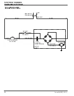

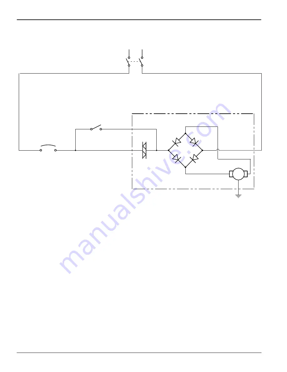
ELECTRICAL DIAGRAMS
DIAGRAMAS ELECTRICAS
Tennant 2260/2270 (07–03)
28
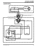
120V LADDER DIAGRAM
DIAGRAMA ESCALONADO
P/N: 1000209
CIRCUIT BREAKER
BLACK
17A
BLACK
MOTOR
801474
RED/ORANGE
P/N: 606292
TRIAC
RECTIFIER
BLACK
L1
BLACK
SW DPST
SW SPST
BLACK
P/N: 99916592
MAIN SWITCH
SW5
WHITE
DC MOTOR
L2
+
+
–
–
P/N 190744
SPEED CONTROL
P/N 190753