background image

Summary of Contents for 242E

Page 1: ......

Page 2: ...ted with reasonable care D The machine is maintained regularly per the maintenance instructions provided D The machine is maintained with Tennant Company supplied or equivalent parts Parts and supplies may be ordered by phone or mail from any Tennant Company parts and service center distributor or from any of the Tennant Company subsidiaries Before ordering parts or supplies be sure to have your m...

Page 3: ...op Machine Go Slow On Grades And Slippery Surfaces Use Care When Backing Machine Move Machine With Care When Hopper Is Raised Make Sure Adequate Clearance Is Available Before Raising Hopper Do Not Carry Riders On Machine Always Follow Safety And Traffic Rules 5 Before Leaving Or Servicing Machine Stop On Level Surface Set Parking Brake Turn Off Machine And Remove Key 6 When Servicing Machine Avoid...

Page 4: ...ER CHARGING LABEL LOCATED ON THE UNDERSIDE OF THE BATTERY COVER HOPPER SUPPORT BAR LABEL LOCATED ON HOPPER SUPPORT BAR BOTH HOPPER LIFT ARMS AND CENTER PANEL LOW DUMP MODEL ONLY HOPPER IS RAISED LABEL LOCATED ON THE LINTEL MULTI LEVEL DUMP MODEL ONLY HOPPER SUPPORT BAR LABEL LOCATED ON THE HOPPER SUPPORT BOTH HOPPER LIFT ARMS AND CENTER PANEL MULTI LEVEL DUMP MODEL ONLY LIFT ARM CLEARANCE LABEL LO...

Page 5: ...MP LEVER 2 8 STEERING WHEEL 2 8 SIDE BRUSH POSITION LEVER 2 8 HOPPER SUPPORT BAR 2 8 SCRUB BRUSH POSITION LEVER 2 8 SOLUTION FLOW KNOBS 2 9 CIRCUIT BREAKER AND FUSES 2 9 Page MACHINE OPERATION 2 10 NORMAL SWEEPING OPERATION 2 10 PRE START CHECKLIST 2 10 TO START MACHINE 2 10 TO SWEEP 2 10 TO DUMP HOPPER 2 11 POST OPERATION CHECKLIST MOTOR OPERATING 2 11 TO STOP MACHINE 2 11 POST OPERATION CHECKLIS...

Page 6: ...6 3 17 HYDRAULIC SCHEMATIC MULTI LEVEL DUMP For machines serial number 005106 and above 3 18 ELECTRICAL SYSTEM 3 19 BATTERIES 3 19 BATTERY CHARGING 3 20 TO CHARGE BATTERIES 3 20 ELECTRIC MOTORS 3 21 ELECTRIC SCHEMATIC 3 22 Page BELTS AND CHAINS 3 23 PUMP BELT 3 23 TO REPLACE PUMP BELT 3 23 COUNTERSHAFT BELT 3 23 MAIN BRUSH BELT 3 24 VACUUM FAN BELT 3 24 SCRUB ATTACHMENT VACUUM FAN BELT 3 24 STATIC...

Page 7: ...4 Hydraulic System 5 26 Page Fig 15 Hydraulic System 5 27 Fig 16 Main Control Valve Group 5 28 Fig 17 Hydraulic Reservoir Assembly 5 29 Fig 18 Directional Control Group 5 30 Fig 19 Directional Control Group 5 32 Fig 20 Rear Drive Wheel Motor Group 5 34 Fig 21 Hopper Lift Cylinder and Side Brush Motor Group 5 35 Fig 22 Rear Drive Wheel and Support Group 5 36 Fig 23 Battery Wire Harness Group 5 37 F...

Page 8: ... Motor Enclosure Band Kit 8 26 Fig 25 Motor Enclosure Band Kit 8 26 Fig 26 Motor Enclosure Band Kit 8 26 Fig 27 Squeegee Blade Kit 8 26 Fig 28 Hopper Dolly Assembly Low Dump 8 27 Fig 29 Scrub Vacuum Fan Drive Group EE 8 28 Fig 30 Vacuum Fan Assembly EE 8 30 Fig 31 Solution and Recovery Tanks Group EE 8 32 Fig 32 Main Scrub Brush Drive Group EE 8 34 Fig 33 Scrub Tank Frame Group EE 8 36 Fig 34 Dete...

Page 9: ...SPECIFICATIONS 1 3 POWER TYPE 1 3 POWER TRAIN 1 3 STEERING 1 3 HYDRAULIC SYSTEM 1 3 BRAKING SYSTEM 1 4 SUSPENSION SYSTEM 1 4 SYSTEM FLUID CAPACITIES 1 4 GENERAL MACHINE DIMENSIONS CAPACITIES 1 4 MACHINE WEIGHTS 1 4 GENERAL MACHINE PERFORMANCE 1 4 MACHINE DIMENSIONS 1 5 ...

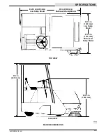
Page 10: ...SPECIFICATIONS 242E MM243 9 89 1 2 ...

Page 11: ...rpm Propelling system relief pressure for machines below serial number 005106 3000 psi 20685 kPa Propelling system relief pressure for machines serial number 005106 and above 2750 psi 17238 kPa Pump accessories for machines below serial number 005106 vane type 2 gpm 7 6 L min 1200 rpm Pump accessories for machines serial number 005106 and above gear type 4 8 gpm 18 L min 2500 rpm Side brush and ho...

Page 12: ...4 in 2070 mm Height with cab and hazard light 90 70 in 2300 mm Track 46 5 in 1180 mm Wheel base 40 in 1015 mm Main brush diameter 14 in 355 mm Main brush length 42 in 1070 mm Side brush diameter 21 in 535 mm Sweeping path width 42 in 1070 mm Sweeping path width with side brush 53 in 1345 mm Hopper capacity 14 ft 0 4 m 1000 lb 455 kg Dust filter area 110 ft 10 2 m MACHINE WEIGHTS GVWR low dump mode...

Page 13: ...3 5 92 TOP VIEW SIDE VIEW 50 75 in 1290 mm 56 75 in 1440 mm Low Dump Model 57 75 in 1470 mm Multi Level Dump Model 86 50 in 2200 mm Low Dump Model 93 in 2360 mm Multi Level Dump Model 81 4 in 2070 mm 05183 05539 MACHINE DIMENSIONS ...

Page 14: ...SPECIFICATIONS 242E MM243 9 89 1 6 ...

Page 15: ... OPERATION 2 10 NORMAL SWEEPING OPERATION 2 10 PRE START CHECKLIST 2 10 TO START MACHINE 2 10 TO SWEEP 2 10 TO DUMP HOPPER 2 11 POST OPERATION CHECKLIST MOTOR OPERATING 2 11 TO STOP MACHINE 2 11 POST OPERATION CHECKLIST MOTOR STOPPED 2 12 TO ENGAGE HOPPER SUPPORT BAR 2 12 TO DISENGAGE HOPPER SUPPORT BAR 2 13 OPERATION ON GRADES 2 13 NORMAL SCRUBBING OPERATION 2 13 PRE START CHECKLIST 2 13 TO START...

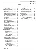
Page 16: ...OPERATION 242E MM243 5 92 2 2 ...

Page 17: ...pproved hydraulic fluid See HYDRAULICS in the MAINTENANCE section 5 Check to be sure the fusible link on the filter box fire door has not been broken during shipment If replacement is necessary see TO REPLACE HOPPER FUSIBLE LINK in the MAINTENANCE section 6 Check the batteries electrolyte level as described in BATTERIES in the MAINTENANCE section A B 03700 CHECKING BATTERY ELECTROLYTE LEVEL A Batt...

Page 18: ...0 05542 MACHINE COMPONENTS A Side Brush H Battery B Hopper Front Access Door I Scrub Attachment C Hopper Cover J Solution Tank Cover D Steering Wheel K Side Scrub Brush E Instrument Panel L Side Squeegee F Operator Seat M Scrub Brush Position Lever G Battery Cover N Solution Flow Knobs ...

Page 19: ...Scrub Brush Switch C Parking Brake M Scrub Vacuum Switch D Main Brush Down Pressure Knob N Key Operated On Off Switch E Hopper Lift and Side Brush Lever O Start Switch F Filter Shaker Switch P Main Brush Position Lever G Vacuum Control Handle Q Hopper Dump Lever H Operating Lights Switch R Steering Wheel I Hour Meter S Side Brush Position Lever J Voltmeter ...

Page 20: ...ETY Before Leaving Or Servicing Machine Stop On Level Surface Set Parking Brake Turn Off Machine And Remove Key MAIN BRUSH DOWN PRESSURE KNOB The main brush down pressure knob adjusts the main brush contact with the floor By turning the pressure knob the main brush contact with the floor will increase or decrease A B 07312 MAIN BRUSH DOWN PRESSURE KNOB A Down Pressure Knob B Main Brush Position Le...

Page 21: ...hazard light accessory The switch turns on and off the hazard light SCRUB BRUSH SWITCH The scrub brush switch is present on a machine equipped with a scrub attachment The scrub brush switch turns on and off the scrub brush SCRUB VACUUM SWITCH The scrub vacuum switch is present on a machine equipped with a scrub attachment The scrub vacuum switch turns on and off the scrub vacuum system KEY OPERATE...

Page 22: ...lot To raise the side brush pull the lever back and to the left into the short slot NOTE Always raise the side brush when it is not in operation HOPPER SUPPORT BAR The hopper support bar is located on the operator s side of the hopper It holds the hopper in a RAISE HOPPER position to allow work to be done under the hopper Do not rely on the machine hydraulic system to keep the hopper raised WARNIN...

Page 23: ...rload which caused the circuit breaker to trip is still present in the circuit the circuit breaker will continue to stop current flow until the overload is corrected Fuses are a one time circuit protection device designed to stop the flow of current in the event of a circuit overload Never substitute higher value fuses than those specified in this manual The circuit breaker is located inside the i...

Page 24: ...and adjustment Check brakes and controls for proper operation Check service records to determine service requirements TO START MACHINE NOTE Before starting machine perform the pre start checks 1 The machine operator must be in the operator s seat with the directional pedal in the neutral position and with a foot on the brake pedal or with the parking brake engaged FOR SAFETY Before Starting Machin...

Page 25: ...l Machines Push the hopper lift and side brush lever forward into the RAISE HOPPER position to dump the hopper Push the lever into the HOLD HOPPER position to keep the hopper in the dumped position Multi Level Dump Model Machines Push the hopper lift and side brush lever forward into the RAISE HOPPER position to lift the hopper to the desired height Be aware The minimum ceiling clearance needed to...

Page 26: ...king brake and start the machine FOR SAFETY Before Leaving Or Servicing Machine Stop On Level Surface Set Parking Brake Turn Off Machine And Remove Key 2 Fully raise the hopper 3 Lift and position the hopper support bar under the hopper lift arm pin on low dump models or hopper lift arm cam on multi level dump models A B 02488 ENGAGED HOPPER SUPPORT BAR LOW DUMP MODEL A Lift Arm Pin B Support Bar ...

Page 27: ...ing draining recovery tank and emptying hopper post operation checklist motor operating stopping machine and post operation checklist motor stopped PRE START CHECKLIST lists things to check before starting the machine TO START MACHINE lists the steps required to start the machine TO SCRUB lists things to keep in mind before and during the scrubbing operation TO DRAIN RECOVERY TANK AND EMPTY HOPPER...

Page 28: ...sible Avoid bumping into posts or scraping the sides of the machine Floor conditions amount of soilage type of soilage brush action and squeegee action all play an important role in determining the type and concentration of detergent to be used For specific recommendations consult the local Tennant Company Representative WARNING Flammable Materials Can Cause An Explosion Or Fire Do Not Use Flammab...

Page 29: ...2 Pull out the solution flow knobs to be used to start the solution flow to the floor 13 Lower the rear squeegee placing the lever in the notch for proper down pressure 14 Scrub as required Adjust the solution flow to match floor conditions When the solution tanks empty or the recovery tank ball float stops vacuum return to the solution dump filling site Drain the recovery tank empty the hopper an...

Page 30: ... brush position lever into the raised position and raise the side brush and side squeegee with the side brush position lever 4 Place the hopper lift and side brush lever in the OFF LOWER HOPPER position 5 Turn off the scrub attachment vacuum system with the scrub vacuum switch 6 Turn off the scrub brush with the scrub brush switch 7 Raise the scrub brush 8 Raise the rear squeegee 9 Set the machine...

Page 31: ...aulic oil temperature too high oil too thin May be caused by operating with excessive load or drag or worn pump Use TENNANT Hydraulic Fluid Check pump See HYDRAULIC COMPONENT TROUBLESHOOTING Worn hydraulic pump or rear drive wheel motors See HYDRAULIC COMPONENTS for parts information Hopper dumps slowly or will not dump Pump drive belts loose Check belt tension not dump Load in hopper too heavy Em...

Page 32: ...g brushes Sweeping brushes worn Replace brushes Dust skirts not adjusted or worn Replace or adjust dust skirts Filters clogged Clean filters Main brush drive belts slipping Check both brush drive belts for proper tension Side brush hydraulic motor worn Check motor Brush driving plugs worn or damaged Check plugs ...

Page 33: ...ace hose Poor vacuum Check vacuum fan and motor on scrub attachment Water spills from side of scrub attachment Side squeegee blade worn or damaged Replace side squeegee blade Too much solution being applied Turn off solution flow 5 to 10 feet before making a turn Little or no solution flow to floor Solution tank empty Fill solution tank floor Water valve cables broken or jammed Replace or free cab...

Page 34: ...Turn off the machine and set the machine parking brake FOR SAFETY Before Leaving Or Servicing Machine Stop On Level Surface Set Parking Brake Turn Off Machine And Remove Key 3 Block the tires which are not being jacked up in order to secure the machine position FOR SAFETY When Servicing Machine Block Machine Tires Before Jacking Machine Up 4 Use a jack of adequate capacity to raise the machine Jac...

Page 35: ...batteries 3 Raise the main brush and side brushes 4 Park the machine on a level surface in a cool dry area 5 Turn off the machine and set the machine parking brake FOR SAFETY Before leaving or servicing machine stop on level surface set parking brake turn off machine and remove key 6 Check the hydraulic fluid level It should be up to the full mark on the dipstick to prevent excessive condensation ...

Page 36: ...behind the bottom edge of the hopper A B 02751 HOPPER DOLLY A Hopper B Dolly 6 Tilt the lift arm hooks back away from the lift arm pins A B 02752 LIFT ARM HOOK A Pin B Hook 7 Place the hopper lift and side brush lever in the OFF LOWER HOPPER position to lower the hopper onto the dolly 8 Disconnect the filter shaker motor wire between the hopper and the machine 9 Push the lift arms down to clear th...

Page 37: ...rush and squeegee and the rear squeegee The scrub attachment and side scrub brush and squeegee are to be removed when sweeping The rear squeegee may be left on the machine if the rear squeegee is raised during machine operation The scrub attachment takes the place of the sweeping hopper The side scrub brush and squeegee take the place of the side sweep brush The main sweeping brush is also exchang...

Page 38: ...NING Raised Hopper May Fall Engage Hopper Support Bar 12 Pull out the locking knobs on the two 2 rear support legs swing the legs up and release the knobs A B 02754 SCRUB ATTACHMENT LEG A Locking Knob B Support Leg 13 Loosen the scrub locking cam on the right lift arm and rotate it snug against the bracket on the scrub attachment Tighten the cam bolt 14 Check to see that the solution recovery hose...

Page 39: ...in brush with a scrubbing main brush as described in TO REPLACE MAIN BRUSH TO REMOVE SCRUB ATTACHMENT 1 Drain the scrub attachment solution and recovery tanks ATTENTION The solution and recovery tanks must be empty during scrub attachment installation and removal to avoid personal injury 2 Drive the machine to the scrub attachment storage area 3 Turn off the machine and set the machine parking bra...

Page 40: ... support bar in its storage location and lower the scrub attachment Turn off the machine 11 Raise the front bumper 12 Start the machine raise the scrub attachment slightly 13 Pull out locking knobs on the two 2 front support legs swing the legs down into the down position and release the knobs 14 Lower the scrub attachment to the floor Turn off the machine 15 Tilt the lift arm hooks back away from...

Page 41: ... For machines below serial number 005106 3 17 HYDRAULIC SCHEMATIC MULTI LEVEL DUMP For machines serial number 005106 and above 3 18 Page ELECTRICAL SYSTEM 3 19 BATTERIES 3 19 BATTERY CHARGING 3 20 TO CHARGE BATTERIES 3 20 ELECTRIC MOTORS 3 21 ELECTRIC SCHEMATIC 3 22 BELTS AND CHAINS 3 23 PUMP BELT 3 23 TO REPLACE PUMP BELT 3 23 COUNTERSHAFT BELT 3 23 MAIN BRUSH BELT 3 24 VACUUM FAN BELT 3 24 SCRUB...

Page 42: ...OLUTION DISTRIBUTION SYSTEM 3 39 SCRUB BRUSHES 3 39 TO REPLACE SCRUB BRUSH 3 40 TO CHECK AND ADJUST SCRUB BRUSH PATTERN 3 41 RECOVERY TANK 3 42 TO DRAIN THE RECOVERY TANK 3 42 TO CLEAN THE RECOVERY TANK 3 43 DEBRIS HOPPER 3 43 SIDE SQUEEGEE 3 44 TO REPLACE SIDE SQUEEGEE BLADE 3 44 REAR SQUEEGEE 3 45 TO REPLACE OR ROTATE REAR BLADE 3 45 TO CHECK AND ADJUST REAR SQUEEGEE 3 47 ...

Page 43: ...ocedures are recommended 1 Check the floor skirts to floor clearance See SKIRTS AND SEALS in the MAINTENANCE section 2 Check the side brush pattern and main brush patterns See BRUSHES in the MAINTENANCE 3 Torque the rear wheel nuts 4 Perform all 50 hour interval lubrication and maintenance procedures listed in the MAINTENANCE CHART ...

Page 44: ...Scrub attachment Check squeegee for damage 1 wear and adjustment Check scrub brush for damage 1 wear and adjustment Lubricate debris hopper pivots SPL 2 50 Hours 8 Hopper lift arm pivots Lubricate SPL 2 3 Countershaft belt idler Lubricate SPL 1 7 Main brush Rotate end for end 1 6 Pump belt Check condition 1 5 Vacuum fan belt Check condition 1 3 Main brush belt Check tension and condition 1 3 Count...

Page 45: ...l Check and adjust travel 1 Scrub attachment Lubricate casters SPL 4 250 Hours 14 Propelling motor Check brushes 1 Scrub attachment Check brushes on scrub brush 2 and vacuum fan motors 500 Hours 1 Hydraulic fluid reservoir Change hydraulic fluid HYDO 1 15 Hydraulic fluid filter Change filter element 1 16 Rear wheel support Lubricate SPL 1 bearing 17 Front wheel bearings Inspect and lubricate SPL 2...

Page 46: ... square head plug has been provided on the front side of the steering gear to check the grease level and to allow filling Check the steering grease level after every 100 hours of operation Fill the unit with SAE 90 weight gear lubricant FRONT WHEEL BEARINGS The front wheel bearings support the front half of the machine Inspect the bearings for contamination seal damage and repack after every 500 h...

Page 47: ... every 50 hours of operation Use Lubriplate EMB grease TENNANT part no 01433 1 A B 02478 LEFT SIDE HOPPER LIFT BEARING A Grease Fitting B Lift Bearing HOPPER DOOR LATCHES The hopper door latches latch the hopper door on multi level dump model machines Two grease fittings are used to lubricate the hopper door latches One grease fitting is on each of the latches To gain access to the latch grease fi...

Page 48: ...r lubricant SCRUB ATTACHMENT LEG CASTERS The scrub attachment casters support the scrub attachment when it is not mounted to the machine A grease fitting is mounted to the axle of each of the four casters Lubricate the casters with a grease gun after every 200 hours of operation Use Lubriplate EMB grease TENNANT part no 01433 1 A B 02754 LEG CASTER A Leg B Grease Fitting SCRUB ATTACHMENT DEBRIS HO...

Page 49: ...se premature failure of hydraulic components ATTENTION Hydraulic components depend on system hydraulic fluid for internal lubrication If dirt or other contaminants are allowed to enter the hydraulic system malfunctions accelerated wear and damage will result HYDRAULIC FLUID RESERVOIR Hydraulic fluid is stored in the hydraulic fluid reservoir The reservoir holds 5 gal 19 L of hydraulic fluid The re...

Page 50: ...ir breather filler cap 3 Pour 5 gal 19 L of new approved hydraulic fluid through a 200 mesh screened funnel and into the reservoir filler neck ATTENTION Use only new approved hydraulic fluid to fill the hydraulic fluid reservoir 4 Check the level in the reservoir with the reservoir dipstick 5 Add hydraulic fluid until the level in the reservoir is between the ADD and FULL range Do not overfill NOT...

Page 51: ... a hydraulic pump or when system contamination is likely change the hydraulic fluid in the reservoir and the hydraulic fluid filter Then the proper start and break in procedure must be followed to prevent possible damage to the pump TO START AND BREAK IN HYDRAULIC PUMP outlines the procedure TO START AND BREAK IN HYDRAULIC PUMP 1 Turn off the machine set the machine parking brake and block the fro...

Page 52: ...vel Surface Set Parking Brake And Turn Off Machine And Remove Key 2 Block the machine tires and jack up the rear of the machine at the designated locations FOR SAFETY When Servicing Machine Block Machine Tires Before Jacking Machine Up 3 Block up the machine with hack stands near the designated locations Make sure the rear tire clears the floor by 2 in 50 mm and all obstacles within a 24 in 610 mm...

Page 53: ...r cam retaining nut repositioning the roller cam and tightening the roller cam retaining nut A B C 00574 SPEED LIMITER A Speed Limiter Cam B Retaining Nut C Pump Linkage HYDRAULIC FLUID LEAKS Fluid escaping from a very small hole can be almost invisible Use a piece of cardboard or wood rather than hands to search for suspected leaks A B C 00002 HYDRAULIC PINHOLE LEAK A Cardboard B Pinhole Leak C M...

Page 54: ...filter element or cartridge Hydraulic motor will not turn over Shaft seized in housing Replace housing and shaft assembly over Large contaminating particles in hydraulic fluid Flush out system change fluid and fluid filter Broken shaft Replace shaft Hydraulic motor runs without turning the shaft Broken parts in motor Disassemble motor and check parts Hydraulic motor leaks at shaft Worn or cut shaf...

Page 55: ...R LIFT CYLINDER FILTER 25 PSI PROPELLING PUMP 45 PSI 3000 PSI 3000 PSI PROPELLING MOTOR 17 7 IN 8 GPM 2400 RPM 8 IN 0 2 01 IN RESERVOIR LINE THROTTLE VALVE CONTROL VALVE 2000 PSI IN OUT B A 05545 HYDRAULIC SCHEMATIC LOW DUMP For machines below serial number 005106 ...

Page 56: ...TOR 4 46 IN HOPPER LIFT CYLINDER FILTER 25 PSI PROPELLING PUMP 2750 PSI 2750 PSI PROPELLING MOTOR RESERVOIR LINE THROTTLE VALVE CONTROL VALVE 2000 PSI 7 5 GPM IN OUT B A 07399 HYDRAULIC SCHEMATIC LOW DUMP For machines serial number 005106 and above ...

Page 57: ...OPELLING MOTOR 17 7 IN 8 GPM 2400 RPM 8 IN 0 2 01 IN SIDE BRUSH MOTOR 4 46 IN HOPPER LIFT CYLINDER LINE THROTTLE VALVE CONTROL VALVE 2000 PSI IN OUT B A ROLL OUT VALVE 2500 PSI IN OUT B A BYD DUMP CYLINDER DUMP CYLINDER 05546 HYDRAULIC SCHEMATIC MULTI LEVEL DUMP For machines below serial number 005106 ...

Page 58: ...750 PSI PROPELLING MOTOR SIDE BRUSH MOTOR 4 46 IN HOPPER LIFT CYLINDER LINE THROTTLE VALVE CONTROL VALVE 2000 PSI IN OUT B A ROLL OUT VALVE 2500 PSI 10 GPM IN OUT B A BYD DUMP CYLINDER DUMP CYLINDER 07400 HYDRAULIC SCHEMATIC MULTI LEVEL DUMP For machines serial number 005106 and above ...

Page 59: ...cts off the top of the batteries as they may cause a short circuit Replace worn or damaged wires Check the electrolyte level in each battery cell before and after charging the batteries and after every 50 hours of operation Never add acid to batteries only distilled water Do not overfill Keep vent plugs firmly in place at all times except when adding water or taking hydrometer readings FOR SAFETY ...

Page 60: ... electrical connections TO CHARGE BATTERIES 1 Stop the machine on a flat dry surface next to the charger and set the machine parking brake Turn off the machine FOR SAFETY Before Leaving Or Servicing Machine Stop On Level Surface Set Parking Brake And Turn Off Machine And Remove Key 2 Remove the seat cushion from the operator seat and tilt it forward Open the battery cover WARNING Batteries Emit Hy...

Page 61: ... should be 0 25 in 5 mm below the bottom of the filling hole 11 Close the battery cover Lower the operator seat and replace the seat cushion ELECTRIC MOTORS There are three electric motors on the machine The propelling motor scrub attachment vacuum fan motor and the scrub attachment scrub brush motor The electric motors are repairable Blow out the dust and inspect the motor brushes in the motors a...

Page 62: ...MAINTENANCE 242E MM243 5 92 3 22 05805 ELECTRIC SCHEMATIC ...

Page 63: ...ng Bracket F Spring 4 Turn down the slotted nut until the pump belt is loose enough to remove 5 Install the new pump belt Adjust the pump and pump mounting bracket position so that the spring length is 6 0 0 1 in 150 3 mm with the slotted nut backed off 6 Back off the slotted nut to the top of yoke until the cotter pin hole lines up with a slot on the nut 7 Install the cotter pin COUNTERSHAFT BELT...

Page 64: ...ours of operation The vacuum fan belt tension is maintained by a spring on the vacuum fan mounting No adjustment is necessary SCRUB ATTACHMENT VACUUM FAN BELT The scrub attachment vacuum fan belt transfers power from the vacuum fan electric motor to the vacuum fan assembly on the EE model machine Check the belt condition every 50 hours of operation The vacuum fan belt tension is maintained by a sp...

Page 65: ...on of the arrows This may be done with the dust filter in the machine Always wear eye protection when using compressed air WATER Soak the dust filter in a water and mild detergent solution Rinse the dust filter until it is clean The maximum water pressure allowable is 40 psi 275 kPa Air dry the wet dust filter do not use compressed air NOTE Be sure the dust filter is dry before reinstalling it in ...

Page 66: ...tween the hopper fire door and the hopper cover It is mounted inside the hopper cover Check the fusible link after every 100 hours of operation If loss of dust control is noticed check the fusible link for breakage or failure due to heat TO REPLACE HOPPER FUSIBLE LINK 1 Turn off the machine and set the machine parking brake FOR SAFETY Before Leaving Or Servicing Machine Stop On Level Surface Set P...

Page 67: ...e Leaving Or Servicing Machine Stop On Level Surface Set Parking Brake And Turn Off Machine And Remove Key B Slide a 0 75 to 0 88 in 20 to 25 mm thick block under each of the rear metal corners of the hopper C Check and adjust the cams on the lift arms so the hopper brackets rest on the cams A B 02479 HOPPER CAM A Cam B Hopper Bracket TO ADJUST MULTI LEVEL DUMP MODEL HOPPER NOTE Empty the debris h...

Page 68: ...on the cylinder rod A B C 00563 HOPPER LIFT CYLINDER A Hopper Lift Cylinder B Jam Nut C Cylinder Clevis B Adjust the cylinder clevis so the cylinder is fully retracted by inserting a pin through the cylinder rod and rotating it C Tighten the clevis jam nut against the clevis 3 HOPPER FLOOR CLEARANCE ADJUSTMENT A Remove the clevis pins connecting the clevis of the hopper dump cylinders to the torqu...

Page 69: ...etely retract the dump cylinders B Turn the machine off and set the machine parking brake FOR SAFETY Before Leaving Or Servicing Machine Stop On Level Surface Set Parking Brake And Turn Off Machine And Remove Key C Loosen the cylinder clevis jam nuts A B C 00595 HOPPER DUMP CYLINDER A Hopper Dump Cylinder B Jam Nut C Cylinder Clevis D Remove clevis pin retaining rings and clevis pins E Adjust the ...

Page 70: ...g action by adjusting latch stop bolt Do not position stop bolt too high or the door will close too tightly and damage the seal and latches A B C 02484 LATCH STOP BOLT A Lift Arm B Stop Bolt C Hopper E Shim the hopper door latching brackets to adjust the hopper door latch engagement and hopper door seal compression Do not compress the seal too much or the door will close too tightly and damage the...

Page 71: ...the brush idler arm off the arm hub 6 Grasp the main brush pull it off the brush drive plug and out of the main brush compartment 7 Place the new or rotated end for end main brush on the floor next to the access door 8 Slide the main brush onto the drive plug Rotate the brush until it engages the drive plug and push it all of the way onto the plug 9 Slide the main brush idler plug onto the main br...

Page 72: ...dth of the main brush pattern To adjust the brush pattern s overall width use the main brush down pressure knob To increase the brush pattern width turn the knob counter clockwise To decrease the brush pattern width turn the knob clockwise SIDE BRUSH The side brush sweeps debris from curbs or gutters into the path of the main brush It should be inspected daily for wear or damage Remove any string ...

Page 73: ...t bar WARNING Raised Hopper May Fall Engage Hopper Support Bar 3 Turn off the machine and set the machine parking brake FOR SAFETY Before Leaving Or Servicing Machine Stop On Level Surface Set Parking Brake And Turn Off Machine And Remove Key 4 Raise the side brush 5 Remove the screw and nut holding the side brush hub on the side brush drive shaft A B 02485 SIDE BRUSH A Side Brush B Retaining Pin ...

Page 74: ... lip retaining strip and worn or damaged hopper lip 7 Thread the retaining strip mounting screws through the retaining strip the hopper lip segment and into the hopper 8 Tighten the mounting screws 9 Start the machine 10 Raise the hopper lower the hopper support bar and lower the hopper 11 Turn off the machine BRUSH DOOR AND SIDE SKIRTS The brush door skirt is located on the bottom of the right ma...

Page 75: ...brush compartment It seals the main brush compartment It should clear the floor by 0 13 in 3 mm The seal should be inspected for wear or damage and adjustment daily TO REPLACE AND ADJUST THE REAR SKIRT 1 Stop the machine on a smooth level surface 2 Turn off the machine and engage the machine parking brake FOR SAFETY Before Leaving Or Servicing Machine Stop On Level Surface Set Parking Brake And Tu...

Page 76: ... the front of the debris compartment The seal should be checked for wear or damage after every 100 hours of operation A B 02480 HOPPER INSPECTION DOOR SEAL A Hopper Inspection Door B Door Seal HOPPER DOOR SEALS The hopper door seals are located around the hopper door opening on multi level dump model machines They seal the hopper door The seals should be checked for wear or damage after every 100 ...

Page 77: ...hould be checked for wear or damage after every 100 hours of operation Check to make sure that the seal is making good contact with the hopper The seal should be compressed 0 12 in 3 mm by the contact A B C D 02465 HOPPER VACUUM FAN SEAL A Lintel B Seal C Mounting Screws D Bracket To adjust seal contact loosen the vacuum fan intake bracket mounting screws Pivot the bracket into the correct positio...

Page 78: ...AFETY Before Leaving Or Servicing Machine Stop On Level Surface And Turn Off Machine And Remove Key 4 Remove the clevis pins from the left and right side brake clevises A B C 02457 BRAKE CLEVIS A Brake Adjusting Clevis B Threaded Rod C Brake Cross Shaft 5 Thread the clevis out to decrease brake pedal height or in to increase brake pedal height Both clevises must be turned the same amount 6 Adjust ...

Page 79: ...ged The spreader tube can be removed from the scrub attachment to be cleaned Remove the solution hoses from the spreader tube Remove the fitting from one end of the tube and slide the tube out of the mounting hangers A brush and hot water may be needed to remove stubborn clogs Do not use water hotter than 130_ F 54_ C A sharp instrument may be used to clear the small distribution holes in the spre...

Page 80: ... Remove the brush idler arm nut A B C 02778 IDLER ARM A Idler Arm B Nut C Scrub Brush 4 Pull the brush idler arm off the arm bracket 5 Pull the scrub brush off the drive hub A B C 02770 REMOVING SCRUB BRUSH A Bracket B Idler Arm C Scrub Brush 6 Align the new scrub brush drive slots with the drive keys on the drive nuts 7 Slide the scrub brush onto the drive hub 8 Slide the idler hub onto the scrub...

Page 81: ...y two minutes It will make a polish mark on the floor 5 Turn off the scrub brush with the scrubber brush switch 6 Release the parking brake and remove the machine from the test area 7 The scrub brush pattern should be 2 in 50 mm across the full length of the brush A B 00582 NORMAL SCRUB BRUSH PATTERN A Scrub Brush Pattern B Pattern To adjust the width of the pattern adjust the position of the lift...

Page 82: ...um The recovery tank should be cleaned after every work shift Two clean out doors have been provided to make the tank cleaning job easier One door is located at the rear of the recovery tank The other door is located at the front of the recovery tank Keep vacuum hoses and nozzles clean Clogged hoses are a common cause of poor water pickup TO DRAIN THE RECOVERY TANK 1 Turn off the machine and set t...

Page 83: ...es are free of dirt and debris which may cause the float to stick 6 Close the clean out doors by positioning the doors against the recovery tank turning the door handles so the four fingers line up behind the tank wall and tighten the lock knob DEBRIS HOPPER The debris hopper collects debris picked up by the main and scrub brushes It is located behind the scrub brush A vacuumized debris screen is ...

Page 84: ...s water into the path of the rear squeegee Check the side squeegee for damage wear and adjustment daily Replace the squeegee blade whenever it becomes damaged or loses its shape or resiliency TO REPLACE SIDE SQUEEGEE BLADE 1 Turn off the machine and set the machine parking brake FOR SAFETY Before Leaving Or Servicing Machine Stop On Level Surface Set Parking Brake And Turn Off Machine And Remove K...

Page 85: ... vacuum fan suction The front squeegee blade channels the water and the rear blade wipes the floor Check the rear squeegee assembly for damage wear and adjustment daily Rotate or replace the front or rear blade of the rear squeegee if its leading edge is worn one half of the way through the thickness of the blade Each front and rear blade has two wiping edges To use them start with one wiping edge...

Page 86: ...ade Remove the front squeegee blade 7 Replace or rotate the squeegee blades Place the back up strip over the rear squeegee blade 8 Position the retaining strips over the front and rear squeegees Mount the squeegee blades with the retaining screws 9 Place the rear squeegee assembly in the machine mounting brackets and mount with the clevis pins Place the cotter pins in the clevis pins to secure the...

Page 87: ...side and deflect 0 75 in 20 mm for smooth floors and 1 25 in 30 mm for rough floors If not continue with step 5 A B 03719 SQUEEGEE DEFLECTION A Squeegee B Deflection NOTE The squeegee blades must be new or have a new wiping edge contacting the floor to correctly adjust the squeegee 5 To level the squeegee tips to the floor adjust the squeegee assembly at the squeegee links 6 To adjust the amount o...

Page 88: ...MAINTENANCE 242E MM243 5 92 3 48 ...

Page 89: ...T TORQUE CHART 4 3 METRIC BOLT TORQUE CHART 4 3 BOLT IDENTIFICATION 4 3 THREAD SEALANT AND LOCKING COMPOUNDS 4 3 HYDRAULIC FITTING INFORMATION 4 4 HYDRAULIC TAPERED PIPE FITTING NPT TORQUE CHART 4 4 HYDRAULIC TAPERED SEAT FITTING JIC TORQUE CHART 4 4 HYDRAULIC O RING FITTING TORQUE CHART 4 4 ...

Page 90: ...APPENDIX 242E MM243 9 89 4 2 ...

Page 91: ...E CHART Thread Class 8 8 Class 10 9 Size Torque ft lb Nm Torque ft lb Nm ______________________________________________________________ M4 2 3 3 4 M5 4 5 6 8 M6 7 9 10 14 M8 18 24 25 34 M10 32 43 47 64 M12 58 79 83 112 M14 94 127 133 180 M16 144 195 196 265 M20 260 352 336 455 M24 470 637 664 900 NOTE Decrease torque by 20 when using a thread lubricant Exceptions to the above chart Rear wheel hub ...

Page 92: ...__________ 0 25 0 44 20 9 ft lb 12 Nm 0 38 0 56 18 20 ft lb 27 Nm 0 50 0 75 16 30 ft lb 41 Nm 0 62 0 88 14 40 ft lb 54 Nm 0 75 1 12 12 70 ft lb 95 Nm 1 0 1 31 12 90 ft lb 122 Nm HYDRAULIC O RING FITTING TORQUE CHART Tube Thread Minimum Maximum O D in Size Torque Torque ______________________________________________________________ 0 25 0 44 20 6 ft lb 8 Nm 9 ft lb 12 Nm 0 38 0 56 18 13 ft lb 18 Nm...

Reviews: