MAINTENANCE
3-59
285 MM191 (6---90)
BRAKES AND TIRES
SERVICE BRAKES
The mechanical service brakes are located on the
front wheels. They are operated by the foot brake
pedal and connecting linkages.
The brake pedal should not travel more than 1 in (25
mm) to fully engage the brakes. Blow the
accumulated dirt from between the brake shoes and
the hub with compressed air through the slots on the
side wheel pockets. Check the brake adjustment
after every 200 hours of operation.
TO ADJUST BRAKE LINKAGE
1. Empty the debris hopper.
2. Park machine on a level surface.
3. Raise the hopper, engage the hopper support
bar, and lower the hopper onto the support bar.
WARNING: Falling hopper. Engage hopper
support bar before working under hopper.
4. Stop the engine.
FOR SAFETY: Before leaving or servicing
machine; stop on level surface, set parking brake,
and turn off machine.
5. Block machine tires.
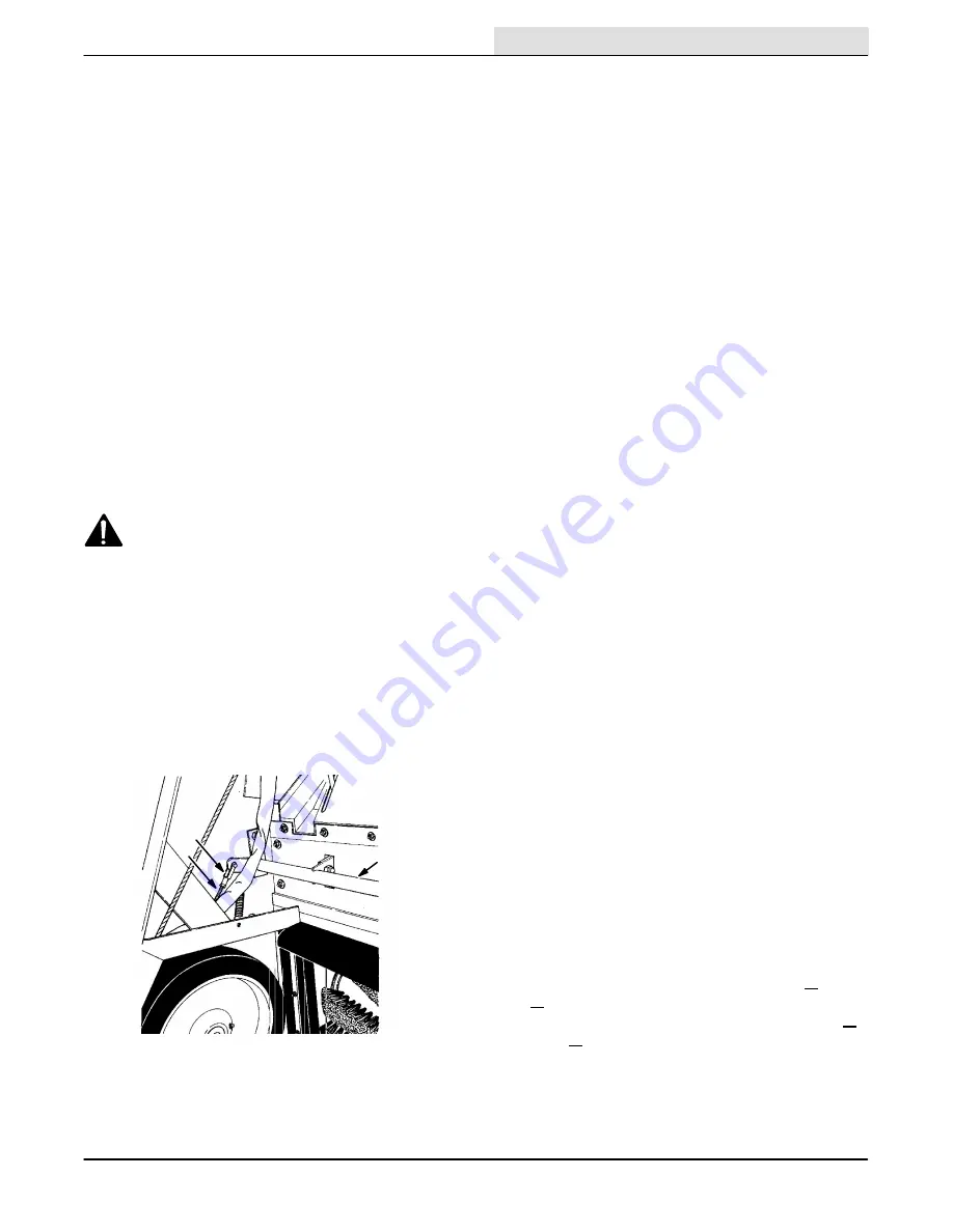
6. Remove the clevis pins from the left and right
side brake clevises.
A
B
C
02457
BRAKE CLEVIS
A. Brake Adjusting Clevis
B. Threaded Rod
C. Brake Cross Shaft
7. Thread the clevis out to decrease brake pedal
height, or in to increase brake pedal height.
Both clevises must be turned the same
amount.
8. Adjust the brake linkage so that the brake
pedal travels no more than 1 in (25 mm) to fully
engage the brakes. If the brake pedal travels
more than 1 in (25 mm), it indicates the brake
clevises are not adjusted the same. Readjust
as necessary.
9. Reinstall the brake clevis pins.
10. Start the engine and raise the hopper.
11. Lower the hopper bar.
12. Lower the hopper and stop the engine.
13. Remove the machine tire blocks.
PARKING BRAKES
The parking brakes are engaged by the parking
brake lever which activates the service brake linkage.
The parking brakes should be adjusted whenever it
becomes very easy to engage the parking brake,
when the machine rolls after engaging the parking
brake, and after every 200 hours of operation. The
parking brake may be routinely tightened by turning
the knurled knob on the end of the parking brake
clockwise. If the knob adjustment is inadequate, fully
loosen the knob and adjust the brake linkage as
described in To Adjust Brake Linkage. Adjust the
parking brake so it will hold the machine on a
smooth 8
_
ramp.
TIRES
The standard front machine tires are solid.
The standard rear machine tire is pneumatic.
Check the tire pressure after every 100 hours of
operation. The proper tire air pressure is 80 + 5 psi
(550 + 35 kPa). When the machine is equipped with
a scrub attachment, the proper air pressure is 70 +
5 psi (480 + 35 kPa).
A solid rear tire is available as an accessory.
Summary of Contents for 285
Page 1: ...r 285 Sweeper Scrubber ...
Page 6: ...ABOUT THIS MANUAL 285 MM191 12 89 d ...
Page 18: ...SPECIFICATIONS 285 MM191 12 89 1 2 ...
Page 22: ...SPECIFICATIONS 285 MM191 12 89 1 6 ...
Page 24: ...OPERATION 2 2 285 MM191 12 89 ...
Page 62: ...OPERATION 2 40 285 MM191 NIL ...
Page 76: ...MAINTENANCE 285 MM191 12 89 3 14 04644 HYDRAULIC SCHEMATIC LOW DUMP MODEL ...
Page 77: ...MAINTENANCE 3 15 285 MM191 12 89 04645 HYDRAULIC SCHEMATIC MULTI LEVEL DUMP MODEL ...
Page 103: ...MAINTENANCE 3 41 285 MM191 6 90 06187 ELECTRICAL SCHEMATIC AUTO SHAKER RFS ...
Page 104: ...MAINTENANCE 285 MM191 6 90 3 42 06187 ELECTRICAL SCHEMATIC AUTO SHAKER RFS ...
Page 134: ...APPENDIX 285 MM191 12 89 4 2 ...


