MAINTENANCE
3-63
285 MM191 (6---90)
RECOVERY TANK
The machine recovery tank stores the water solution
picked up by the machine squeegee and vacuum
fan. The recovery tank is located under the solution
tanks.
The recovery tank should be drained after the
solution tank is empty and whenever the ball float
rises and stops the water vacuum.
The recovery tank should be cleaned after every
work shift.
Two clean-out doors have been provided to make
the tank cleaning job easier. One door is located at
the rear of the recovery tank. The other door is
located at the front of the recovery tank.
Keep vacuum hoses and nozzles clean. Clogged
hoses are a common cause of poor water pickup.
TO DRAIN THE RECOVERY TANK
1. Stop the engine and set the machine parking
brake.
FOR SAFETY: Before leaving or servicing
machine; stop on level surface, set parking brake,
and turn off machine.
2. Open the front access door.
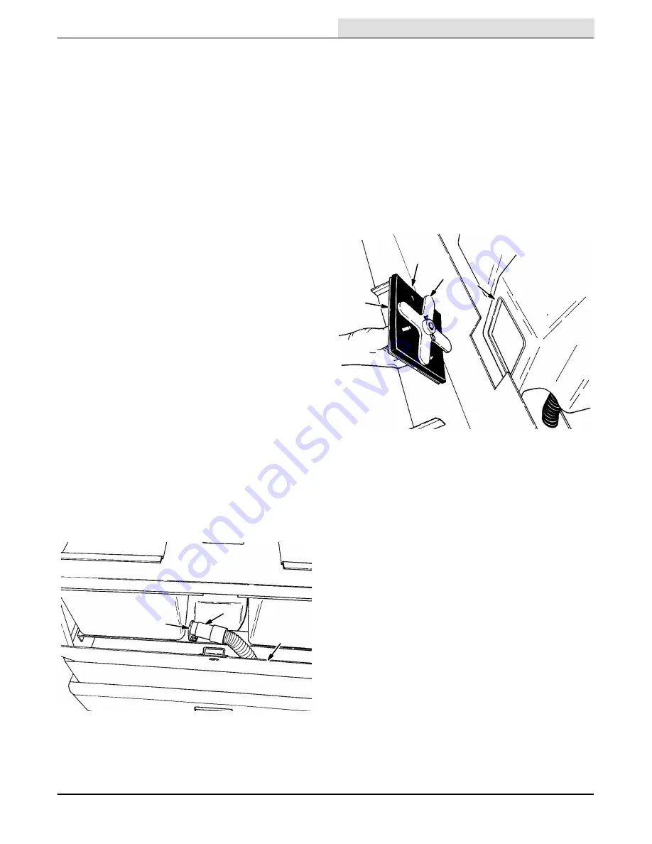
3. Remove the drain hose from its retention plug
and lower it to a floor drain.
NOTE: The tank will not empty with the vacuum fan
operating.
A
B
C
02748
DRAIN HOSE
A. Retention Plug
B. Drain Hose
C. Front Access Door
TO CLEAN THE RECOVERY TANK
1. Stop the engine and set the machine parking
brake.
FOR SAFETY: Before leaving or servicing
machine; stop on level surface, set parking brake,
and turn off machine.
2. Drain the recovery tank.
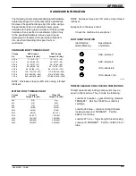
3. Open the front clean out doors by turning the
door handles and pulling the doors away from
the recovery tank.
A
B
C
D
02772
REAR CLEAN-OUT DOOR
A. Clean-Out Door
B. Door Seal
C. Door Fingers
D. Recovery Tank
4. Spray the inside of the tank with clean water.
Remove all sludge and debris from the bottom
of the tank.
Summary of Contents for 285
Page 1: ...r 285 Sweeper Scrubber ...
Page 6: ...ABOUT THIS MANUAL 285 MM191 12 89 d ...
Page 18: ...SPECIFICATIONS 285 MM191 12 89 1 2 ...
Page 22: ...SPECIFICATIONS 285 MM191 12 89 1 6 ...
Page 24: ...OPERATION 2 2 285 MM191 12 89 ...
Page 62: ...OPERATION 2 40 285 MM191 NIL ...
Page 76: ...MAINTENANCE 285 MM191 12 89 3 14 04644 HYDRAULIC SCHEMATIC LOW DUMP MODEL ...
Page 77: ...MAINTENANCE 3 15 285 MM191 12 89 04645 HYDRAULIC SCHEMATIC MULTI LEVEL DUMP MODEL ...
Page 103: ...MAINTENANCE 3 41 285 MM191 6 90 06187 ELECTRICAL SCHEMATIC AUTO SHAKER RFS ...
Page 104: ...MAINTENANCE 285 MM191 6 90 3 42 06187 ELECTRICAL SCHEMATIC AUTO SHAKER RFS ...
Page 134: ...APPENDIX 285 MM191 12 89 4 2 ...


