OPERATION
2-10
285 MM191 (12---89)
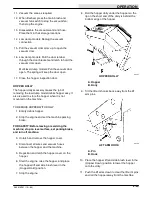
HOPPER LIFT AND SIDE BRUSH LEVER
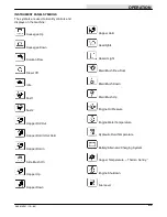
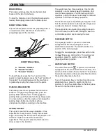
The hopper lift and side brush lever controls the
hopper lift height and side brush rotation.
To lift the hopper, pull the lever back into the
(Hopper Up) position until the hopper reaches
the desired lift height. Be sure adequate vertical
clearance is available before lifting the hopper.
WARNING: Machine hopper lifts to 108 in
(2745 mm) when high dumping. Hopper can
hit overhead wires or object. Electrical shock or
falling debris can result. Be sure adequate
clearance is available before raising hopper.
To hold the hopper up, pull the lever all the way back
into the
(Hopper Hold) position. Do not rely on
the hydraulic system to keep the hopper raised if
work is to be done on the machine. Always engage
the hopper support bar.
WARNING: Falling hopper. Engage hopper
support bar before working under hopper.
To lower the hopper, push the lever into the
(Hopper Down) position.
To the start the side brush rotation, push the lever
into the
(Side Brush On) position. To stop the
side brush rotation, pull the lever into the (Hopper
Down) position.
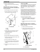
MAIN BRUSH POSITION LEVER
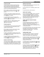
The main brush position lever controls the position of
the main brush. There are two positions in which the
main brush may be operated. The positions are
normal and free-float. The normal sweeping position
is used for most sweeping conditions. Operating in
the normal position will extend main brush life. The
free-float position is used when sweeping extremely
uneven areas. The free-float position allows the main
brush to follow the uneven surfaces more closely.
To lower the main brush for normal sweeping
conditions, pull the lever back and to the left into the
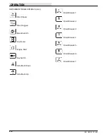
(Main Brush Down) position.
To lower the main brush for sweeping extremely
uneven surfaces, pull the lever back and to the right
into the
(Main Brush Free Float) position.
To raise the main brush, pull the lever all the way
back and to the right into the
(Main Brush Up)
position.
NOTE: Always raise the main brush when the
machine is not being operated for a period of time to
prevent the main brush from taking a set.
STEERING WHEEL
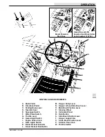
The steering wheel controls the rear wheel through
an arm and tie rod. The machine is very responsive
to steering wheel movements. Use care until you
become more experienced in guiding the machine.
A horn button is located in the center of the steering
wheel.
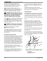
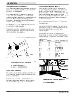
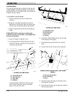
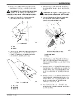
MAIN BRUSH HEIGHT ADJUSTMENT KNOB
The main brush height adjustment knob is located
behind an access door next to the operator’s left
foot. It limits how close to the ground the main brush
will operate when the main brush position lever is in
the “normal” position.
To raise the main brush and reduce the main brush
floor contact, loosen the wing nut and thread the
knob clockwise.
To lower the main brush and increase main brush
floor contact, loosen the locking knob and thread the
knob counter-clockwise. Retighten the wing nut after
making any adjustment.
A
B
00563
MAIN BRUSH HEIGHT ADJUSTMENT KNOB
A. Wing Nut
B. Adjustment Knob
Summary of Contents for 285
Page 1: ...r 285 Sweeper Scrubber ...
Page 6: ...ABOUT THIS MANUAL 285 MM191 12 89 d ...
Page 18: ...SPECIFICATIONS 285 MM191 12 89 1 2 ...
Page 22: ...SPECIFICATIONS 285 MM191 12 89 1 6 ...
Page 24: ...OPERATION 2 2 285 MM191 12 89 ...
Page 62: ...OPERATION 2 40 285 MM191 NIL ...
Page 76: ...MAINTENANCE 285 MM191 12 89 3 14 04644 HYDRAULIC SCHEMATIC LOW DUMP MODEL ...
Page 77: ...MAINTENANCE 3 15 285 MM191 12 89 04645 HYDRAULIC SCHEMATIC MULTI LEVEL DUMP MODEL ...
Page 103: ...MAINTENANCE 3 41 285 MM191 6 90 06187 ELECTRICAL SCHEMATIC AUTO SHAKER RFS ...
Page 104: ...MAINTENANCE 285 MM191 6 90 3 42 06187 ELECTRICAL SCHEMATIC AUTO SHAKER RFS ...
Page 134: ...APPENDIX 285 MM191 12 89 4 2 ...

