OPERATION
2-32
285 MM191 (12---89)
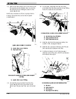
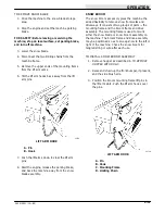
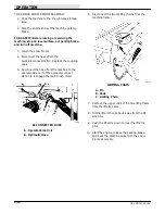
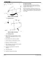
4. Position the upper ends of the mounting frame
over the cams.
5. Secure each upper end of the mounting frame
to the cam with a spacer and bolt provided with
the accessory.
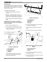
A
B
02760
SECURED MOUNTING FRAME UPPER END
A. Upper End
B. Cam
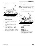
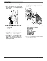
6. Connect the two limiting chains between the
mounting frame and the machine.
7. Connect the snow broom support arm to the
center rear hole in the mounting frame.
8. Connect the snow broom frame to either the
right or left side of the mounting frame with a
clevis pin depending upon which direction the
snow should be swept.
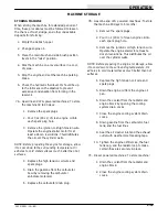
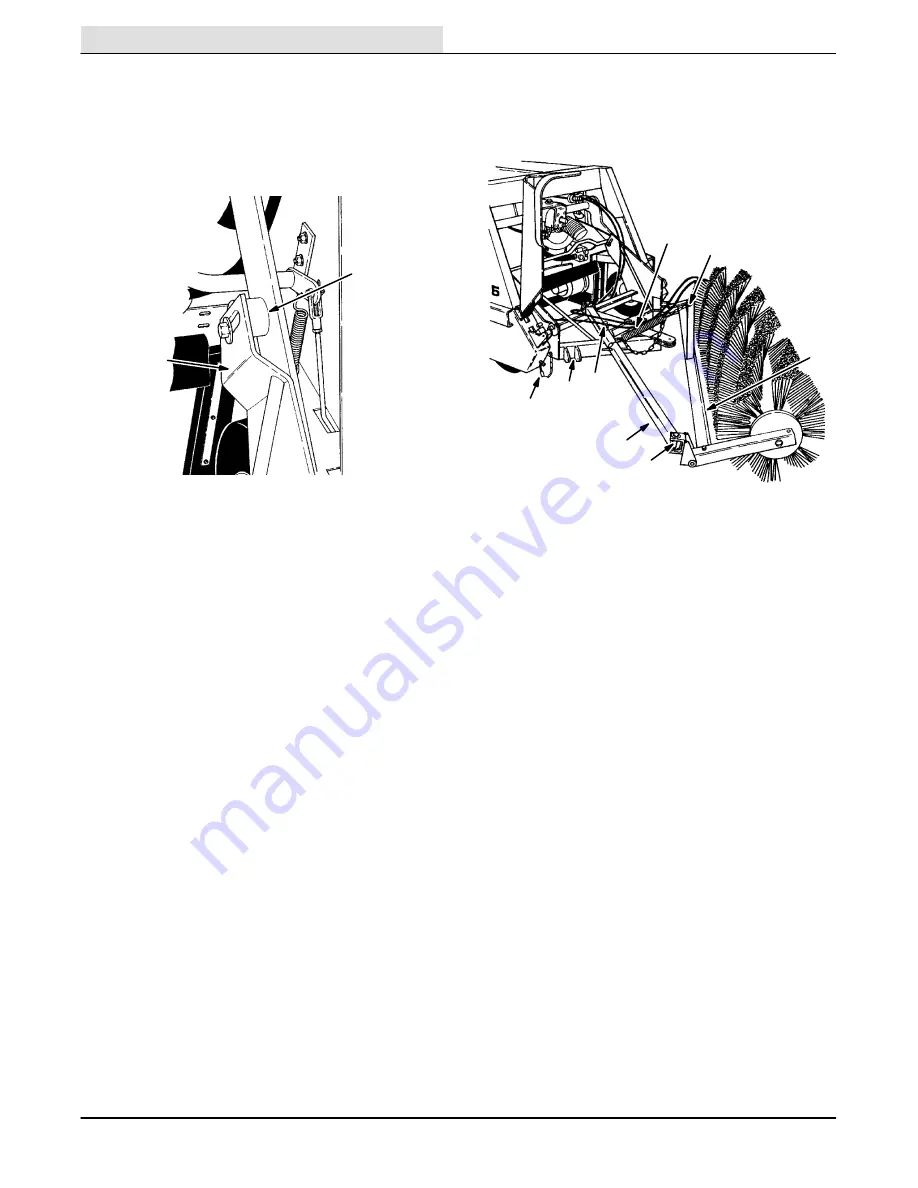
9. Connect the tension chain between the top of
the upright arm and the peg on the support
arm. The tension chain helps raise or lower the
snow broom.
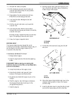
A
B
C
D
E
F
G
H
02762
SNOW BROOM INSTALLATION
A. Tension Chain and Spring
B. Upright Arm
C. Support Arm
D. Clevis Pin
E. Snow Broom Frame
F. Hex Set Screw
G. Mounting Frame
H. Limiting Chain
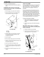
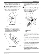
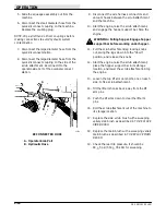
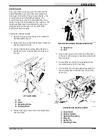
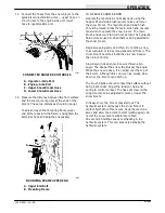
10. Disconnect the hydraulic hose from the front of
the quick-disconnect station.
Summary of Contents for 285
Page 1: ...r 285 Sweeper Scrubber ...
Page 6: ...ABOUT THIS MANUAL 285 MM191 12 89 d ...
Page 18: ...SPECIFICATIONS 285 MM191 12 89 1 2 ...
Page 22: ...SPECIFICATIONS 285 MM191 12 89 1 6 ...
Page 24: ...OPERATION 2 2 285 MM191 12 89 ...
Page 62: ...OPERATION 2 40 285 MM191 NIL ...
Page 76: ...MAINTENANCE 285 MM191 12 89 3 14 04644 HYDRAULIC SCHEMATIC LOW DUMP MODEL ...
Page 77: ...MAINTENANCE 3 15 285 MM191 12 89 04645 HYDRAULIC SCHEMATIC MULTI LEVEL DUMP MODEL ...
Page 103: ...MAINTENANCE 3 41 285 MM191 6 90 06187 ELECTRICAL SCHEMATIC AUTO SHAKER RFS ...
Page 104: ...MAINTENANCE 285 MM191 6 90 3 42 06187 ELECTRICAL SCHEMATIC AUTO SHAKER RFS ...
Page 134: ...APPENDIX 285 MM191 12 89 4 2 ...

