MAINTENANCE
285 MM191 (12---89)
3-24
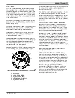
FUEL SYSTEM -- LPG
LPG FUEL SYSTEM
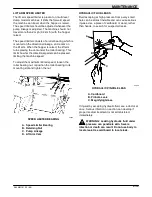
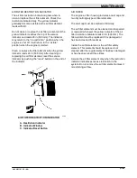
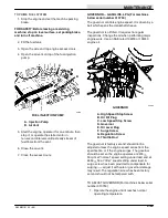
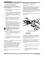
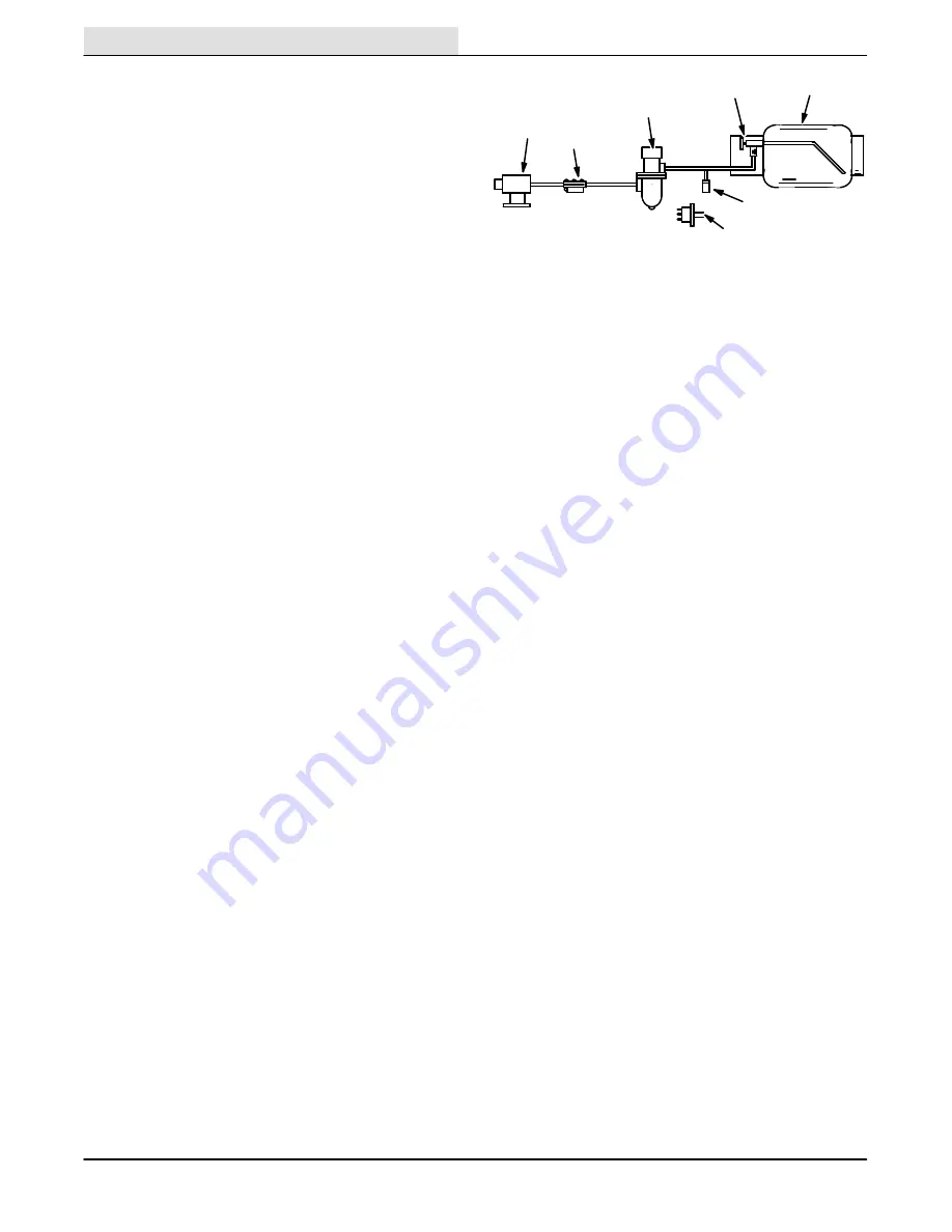
The liquid withdrawal LPG fuel system is made up of
five components which are: the LPG fuel tank,
pressure relief valve, fuel filter lock,
vaporizer-regulator, and the carburetor.
Liquid LPG fuel flows from the LPG tank, under its
own pressure, to the pressure relief valve. This valve
is normally closed, preventing LPG fuel from
escaping into the atmosphere. The valve opens to
relieve pressure if the fuel pressure exceeds system
limits. From the pressure relief valve, the liquid LPG
fuel is piped to the fuel filter lock.
The fuel filter lock filters unwanted tank scale and
deposits out of the LPG fuel. The fuel filter lock also
stops the flow of LPG fuel when the engine is not
operating. The oil pressure switch controls the fuel
filter lock. When the engine oil pressure is
5 psi (35 kPa) or greater, the oil pressure switch
permits an electrical current to open the fuel filter
lock which allows LPG fuel to flow on to the
vaporizer-regulator. The oil pressure switch is
bypassed when the engine is being started, allowing
LPG fuel to flow.
The vaporizer section of the vaporizer-regulator
converts the liquid LPG fuel into a gaseous LPG fuel.
From the vaporizer section, the gaseous LPG fuel is
sent to the primary regulator section of the
vaporizer-regulator. The primary regulator section
reduces the pressure of the LPG fuel. The secondary
regulator section reduces the LPG fuel pressure to
the level required by the carburetor. From the
vaporizer-regulator, the LPG fuel is sent to the
carburetor where it is finally metered into the air flow
which is sent to the engine combustion chamber.
A
B
C
D
E
F
G
03511
LPG FUEL SYSTEM
A. Carburetor
B. Vaporizer-Regulator
C. Fuel Filter Lock
D. Pressure Relief Valve
E. Tank Service Valve
F. LPG Fuel Tank
G. Oil Pressure Switch
Never operate an LPG powered machine if the LPG
fuel system is leaking, or if any component in the fuel
system is malfunctioning. Operating the machine
under either of these conditions may cause a fire or
explosion.
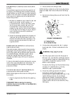
Check for frosting. Frosting does occur before the
engine reaches operating temperature. Check after
engine reaches operating temperature. If frosting
occurs on or near any LPG component, there is a
possibility of an LPG fuel leak or a malfunctioning
component.
To locate the leak, apply a soapy water solution to
the suspected area. Watch for bubbles forming in a
confined area. This area may have an LPG fuel leak.
Repair or replace the part. Use Loctite brand
Stainless Steel PST thread sealant when
reassembling. This epoxy-type sealant is not affected
by aging or high humidity. Be sure to follow
application directions and apply proper torque when
reconnecting fittings.
Never bypass safety components except to test. If
they are defective, replace them before operating the
machine.
Check routings of all LPG hoses. Keep them away
from sharp edges, exhaust manifolds, or other hot
surfaces. Check for signs of abrasion or
deterioration. Replace hoses found to be worn or
damaged.
Summary of Contents for 285
Page 1: ...r 285 Sweeper Scrubber ...
Page 6: ...ABOUT THIS MANUAL 285 MM191 12 89 d ...
Page 18: ...SPECIFICATIONS 285 MM191 12 89 1 2 ...
Page 22: ...SPECIFICATIONS 285 MM191 12 89 1 6 ...
Page 24: ...OPERATION 2 2 285 MM191 12 89 ...
Page 62: ...OPERATION 2 40 285 MM191 NIL ...
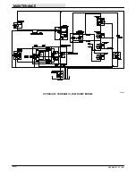
Page 76: ...MAINTENANCE 285 MM191 12 89 3 14 04644 HYDRAULIC SCHEMATIC LOW DUMP MODEL ...
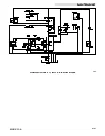
Page 77: ...MAINTENANCE 3 15 285 MM191 12 89 04645 HYDRAULIC SCHEMATIC MULTI LEVEL DUMP MODEL ...
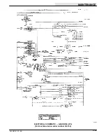
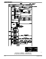
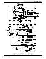
Page 103: ...MAINTENANCE 3 41 285 MM191 6 90 06187 ELECTRICAL SCHEMATIC AUTO SHAKER RFS ...
Page 104: ...MAINTENANCE 285 MM191 6 90 3 42 06187 ELECTRICAL SCHEMATIC AUTO SHAKER RFS ...
Page 134: ...APPENDIX 285 MM191 12 89 4 2 ...

