background image

IB 340513 (10-01)

2

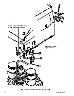
7. Assemble the new solenoid valve (2) to the new mounting bracket (1) with two hex screws

and lock nuts. Tighten hardware to 16--20 ft lbs.

(Refer to FIG. 2)

8. Mount 90

°

water hose (3) to the solenoid valve (2) with wormdrive clamp. Hand tighten the

wormdrive clamp with 5/16 nut driver.

(Refer to FIG. 2)

9. Assemble the set aside pinch lever to the new mounting bracket (1) with a nylon washer

(between the lever and bracket), hex screw, flat washer and lock nut. Hand tighten

hardware. The pinch lever should move with a slight tension.

(Refer to FIG. 2)

10. Mount the new solution valve (2) and bracket (1) assembly to the bottom of the solution

tank, in place of the old assembly. Tighten hardware to 16--20 ft lbs. Connect the 90

°

water

hose (3) to the tank with wormdrive clamp. Hand tighten the wormdrive clamp with 5/16 nut

driver.

(Refer to FIG. 2)

11. Connect the open end of the push pull cable to the pinch lever with the swivel and pan

screw. Hand tighten the securing hardware.

(Refer to FIG. 2)

12. Connect the machine harness 47A/GRY and 13M/BLK to the new solenoid valve (2).

Secure the wire harness to the solenoid valve (2) with a plastic wire tie.

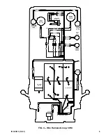
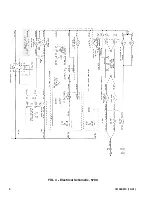
(Refer to FIG. 3 and 4)

13. Replace the front cover on the machine. Disengage the solution tank support rod and lower

the solution tank.

14. Check the machine and new solution control group for proper operation.

BILL OF MATERIALS FOR SOLUTION VALVE REPLACEMENT KIT 374754

TENNANT

Ref.

Part No.

Description

Qty.

1

397787

Bracket, mtg, valve

1

2

374752

Valve, solenoid

1

3

397777

Hose, rbr, E90, 0.62ID 0.81ID (valve)

1

4

374753

Hose, PVC

1

TENNANT COMPANY

P. O. Box 1452

Minneapolis, MN 55440-1452

Summary of Contents for 340513

Page 1: ...e solution tank 2 Move the machine to a clean level surface FOR SAFETY Before leaving or servicing machine stop on level surface and set parking brake Then turn off machine and remove key 3 Remove front cover from machine Set the front cover and mounting hardware aside 4 Locate the solution control group mounted underneath the front of the solution tank 5 Raise the solution tank and engage the sol...

Page 2: ...onnect the 90 water hose 3 to the tank with wormdrive clamp Hand tighten the wormdrive clamp with 5 16 nut driver Refer to FIG 2 11 Connect the open end of the push pull cable to the pinch lever with the swivel and pan screw Hand tighten the securing hardware Refer to FIG 2 12 Connect the machine harness 47A GRY and 13M BLK to the new solenoid valve 2 Secure the wire harness to the solenoid valve ...

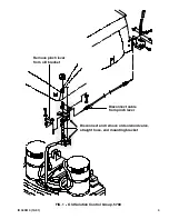
Page 3: ...IB 340513 10 01 3 Disconnect cable from pinch lever Remove pinch lever from old bracket Disconnect and remove old solenoid valve straight hose and mounting bracket FIG 1 Old Solution Control Group 5700 ...

Page 4: ...IB 340513 10 01 4 2 1 3 4 Mount set aside pinch lever to new mounting bracket Reconnect cable to pinch lever FIG 2 New Solution Control Group 5700 ...

Page 5: ...BLK 47A GRY 30 PUR 31 BRN 64A GRY 13EE BLK 13DD BLK 13U BLK 13V BLK 88A BLK 66A GRN UPPER TANK LEVEL SWITCH LOWER TANK ES LEVEL SWITCH 13R BLK 54 BRN 53 GRN 13G BLK 40 GRN 18C YEL 66B GRN 64B BLU LEFT BRUSH MOTOR RIGHT BRUSH MOTOR SOLUTION SOLENOID VALVE 44 PUR 45 GRY 46 GRY 13T BLK 58 BLU GRN BLU BLK RED POWER WAND PUMP HEADLIFT ACTUATOR PROPEL MOTOR VAC FAN BATTERIES 1 FIG 3 Wire Harness Group 5...

Page 6: ...IB 340513 10 01 6 FIG 4 Electrical Schematic 5700 ...

Reviews: