background image

OPERATION

Tennant 5280 (10--04)

11

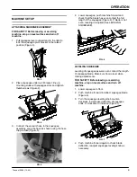
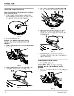
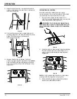
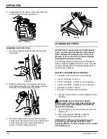
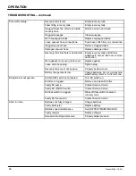
3. Open access cover on scrub head and turn brush

until drive pin is visible (Figure 14).

FIG. 14

4. Press down on the brush lock pin and turn brush

clockwise. The brush will drop off drive plate

(Figure 15).

FIG. 15

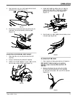
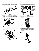
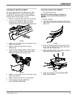
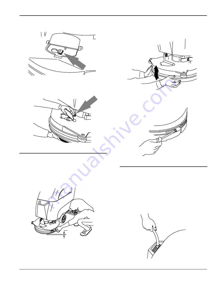
ADJUSTING SCRUB HEAD SKIRT HEIGHT

1. Place machine on a level surface and turn off

machine.

2. Lower scrub head with pad/brush installed.
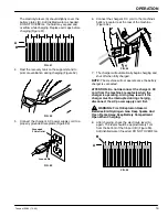
3. Check to see if skirt height is 1.5 mm (.062 in.) from

floor all away around scrub head (Figure 16).

1.5 mm

(.062 in)

FIG. 16

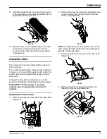
4. Adjust skirt height by sliding skirt up or down by

hand. Skirt band clamp should only be slightly

tightened to allow for easy hand adjustment

(Figure 17).

FIG. 17

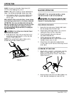
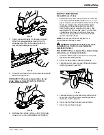
5. If skirt band is too tight, slightly loosen clamp at rear

of scrub head (Figure 18).

FIG. 18

FILLING SOLUTION TANK

1. Push machine to filling site and turn off machine.

FOR SAFETY: Before leaving or servicing

machine, stop on level surface and turn off

machine.

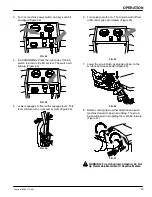
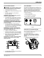
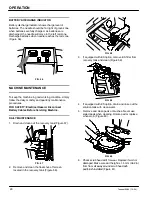
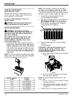
2. Remove the fill--port cover at the front of the

machine and fill solution tank to the opening

screen with clean water, 60

_

C (140

_

F) maximum

(Figure 19).

FIG. 19

Summary of Contents for 5280

Page 1: ...Scrubber 5280 Operator and Parts Manual 610168 Rev 02 10 04 Model No 610678 610679 PAC ...

Page 2: ...y authorized parts and service center distributor or from any of the manufacturer s subsidiaries This machine will provide excellent service However the best results will be obtained at minimum costs if S The machine is operated with reasonable care S The machine is maintained regularly per the maintenance instructions provided S The machine is maintained with manufacturer supplied or equivalent p...

Page 3: ... MONTHLY MAINTENANCE 21 QUARTERLY MAINTENANCE 22 BATTERY MAINTENANCE 22 SQUEEGEE BLADE REPLACEMENT 23 SCRUB HEAD SKIRT REPLACEMENT 23 MACHINE JACKING 24 TRANSPORTING MACHINE 24 STORING MACHINE 24 RECOMMENDED STOCK ITEMS 24 TROUBLESHOOTING 25 SPECIFICATIONS 27 MACHINE DIMENSIONS 27 ELECTRICAL DIAGRAMS 28 PARTS LIST 30 REPLACEMENT BRUSHES AND PAD DRIVER GROUP 30 SOLUTION TANK AND VACUUM MOTOR GROUP ...

Page 4: ...connect Battery Cables Before Servicing Machine WARNING Spinning Brush Keep Hands Away Turn Off Power Before Working On Machine The following information signals potentially dangerous conditions to the operator or equipment FOR SAFETY 1 Do not operate machine With flammable liquids or near flammable vapors as an explosion or flash fire may occur Unless trained and authorized Unless operation manua...

Page 5: ...iler Put the scrub head in the lowered position SAFETY LABELS The safety labels appear on the machine in the locations indicated Replace labels if they are missing or become damaged or illegible WARNING LABEL Located on the recovery tank cover MOVING PARTS LABEL Located on scrub head WARNING Spinning Brush Keep Hands Away Turn Off Power Before Working On Machine READ MANUAL LABEL Located on contro...

Page 6: ...very Tank C Scrub Head D Scrub Head Access Cover E Solution Tank Fill Opening F Batteries G Recovery Tank Cover H Solution Tank Drain Hose I Recovery Tank Drain Hose J Control Console Panel K Recovery Tank Support Stand L Squeegee M Scrub Head Lift Pedal N Scrub Head Release Pedal O Squeegee Leveling Knob ...

Page 7: ...meter Option K On off Key Switch Option L Circuit Breakers M Solution Flow Knob N Solution Tank Drain Hose O Brush Pressure Knob P Brush Pressure Indicator Q Recovery Tank Drain Hose R Charger Plug CONTROL PANEL SYMBOLS Solution Flow Main Power Circuit Breaker Battery Discharge Indicator Vacuum Motor Circuit Breaker Extended Scrub Option Off Aisle Wand Option ES Pump Light Option R Main Power Scru...

Page 8: ...NG Fire Or Explosion Hazard Batteries Emit Hydrogen Gas Keep Sparks And Open Flame Away Keep Battery Hood Open When Charging FOR SAFETY When servicing machine wear protective gloves and eye protection when handling batteries and battery cables Avoid contact with battery acid Recommended Battery Specifications Two 12 volt deep cycle 130 Amp hour lead acid batteries Maximum battery dimensions are 17...

Page 9: ...r squeegee push machine forward and check that the blade has even contact the full length of the squeegee Figure 6 If blade is not even leveling is required See LEVELING SQUEEGEE FIG 6 LEVELING SQUEEGEE Leveling of squeegee assures even contact the length of squeegee blade Make sure floor is level when making adjustments FOR SAFETY Before leaving or servicing machine stop on level surface and turn...

Page 10: ... on front of scrub head Turn drive plate until pin slot is visible Figure 10 FIG 10 5 Place scrub brush under scrub head Make sure one of brush drive pins is facing front Figure 11 FIG 11 6 Align brush drive pin with the drive pin slot on drive plate Lift scrub brush and turn brush counter clockwise to engage drive pins into drive slots Figure 12 FIG 12 7 Check the brush to make sure it is securel...

Page 11: ...or all away around scrub head Figure 16 1 5 mm 062 in FIG 16 4 Adjust skirt height by sliding skirt up or down by hand Skirt band clamp should only be slightly tightened to allow for easy hand adjustment Figure 17 FIG 17 5 If skirt band is too tight slightly loosen clamp at rear of scrub head Figure 18 FIG 18 FILLING SOLUTION TANK 1 Push machine to filling site and turn off machine FOR SAFETY Befo...

Page 12: ... option make sure to activate the ES option ON OFF switch FIG 20 MACHINE OPERATION FOR SAFETY Do not operate machine unless operation manual is read and understood WARNING Fire or Explosion Hazard Never Operate Machine In Or Near Flammable Liquids Vapors Or Combustible Dusts PRE OPERATION CHECKS 1 Sweep floor and pick up any material which could become wrapped around scrub brush 2 Check battery di...

Page 13: ...l also turn on vacuum system Figure 24 FIG 24 6 Turn solution switch on The solution will not flow until control grips are rotated Figure 25 FIG 25 7 Lower the scrub brush by stepping down on the scrub head release pedal Figure 26 FIG 26 8 Rotate control grips in either direction and push machine forward to begin scrubbing The scrub brush will assist in propelling the machine forward Figure 27 FIG...

Page 14: ...TION ES option extends scrubbing time by reusing recovered water The recovered water is filtered and recycled back into the solution tank for reuse 1 Pour up to 23L 6 gal of clean water 60 C 140 F maximum temperature into recovery tank when filling solution tank Figure 31 WARNING Fire Or Explosion Hazard Never Use Flammable Liquids Or Operate Machine In Or Near Flammable Liquids Vapors Or Combusti...

Page 15: ...over when worn 7 If squeegee leaves streaks raise and wipe blades with a cloth Pre sweep area to prevent streaking 8 Observe battery discharge indicator When needle drops to the red zone stop scrubbing and recharge batteries Figure 33 ATTENTION Do not operate machine with battery discharge indicator in this red zone battery damage will result FIG 33 9 ES SCRUBBING Drain tanks and clean ES filter i...

Page 16: ...eel Figure 37 FIG 37 5 Attach vacuum hose and solution hose to wand Figure 38 FIG 38 6 Turn machine power and wand pump switch on Figure 39 FIG 39 7 Lower squeegee to turn on vacuum system Figure 40 FIG 40 8 Squeeze lever on wand and spray solution on floor Scrub floor with brush side of wand and vacuum up solution with squeegee side of wand Figure 41 WARNING Fire Or Explosion Hazard Do Not Pick U...

Page 17: ... cleaned out after every use Transport the machine to a draining site turn the machine off and follow the draining instructions below FOR SAFETY Before leaving or servicing machine stop on level surface and turn off machine DRAINING RECOVERY TANK 1 Remove recovery tank drain hose from hose hook Figure 43 FIG 43 2 Remove the drain hose cap while holding the hose up then slowly lower the drain hose ...

Page 18: ...charged for lengthy periods The following charging instructions are intended for battery chargers supplied with the machine Only use a battery charger with the following specifications to prevent battery damage BATTERY CHARGER SPECIFICATIONS S CHARGER TYPE FOR LEAD ACID BATTERIES S OUTPUT VOLTAGE 24 VOLTS S OUTPUT CURRENT 12 AMPS for 130 AH Batteries S OUTPUT CURRENT 20 AMPS for 215 AH Batteries S...

Page 19: ...e at the rear of the machine Figure 54 FIG 54 7 The charger will automatically begin charging and shut off when fully charged NOTE The machine will not operate once the battery charger is connected ATTENTION Do not disconnect the charger s DC cord from the machine s receptacle when the charger is operating Arcing may result If the charger must be interrupted during charging disconnect the AC power...

Page 20: ... Hazard Disconnect Battery Cables Before Servicing Machine DAILY MAINTENANCE 1 Drain and clean out the recovery tank Figure 57 FIG 57 2 Remove and clean the float shut off screen located in the recovery tank Figure 58 FIG 58 3 If equipped with ES option remove ES filter from recovery tank and clean Figure 59 FIG 59 4 If equipped with ES option drain and rinse out the solution tank with clean water...

Page 21: ...id according to mixing instructions Over a floor drain briefly operate machine ES option and wand option for 30 seconds each Turn machine off and leave machine sit overnight Next day disperse remaining mixture then rinse solution system with clean water NOTE Contact your chemical supplier for a recommended neutralizer liquid WARNING Flammable materials can cause an explosion or fire Do not use fla...

Page 22: ...not be accurate FIG 65 SPECIFIC GRAVITY at 27 C BATTERY CHARGE 1 265 100 CHARGED 1 223 75 CHARGED 1 185 50 CHARGED 1 148 25 CHARGED 1 110 DISCHARGED NOTE If the readings are taken when the battery electrolyte is any temperature other than 27_C 80_F the reading must be temperature corrected Add or subtract to the specific gravity reading 0 004 4 points for each 6_C 43_F above or below 27_C 80_F 2 A...

Page 23: ...p and remove retainer band and squeegee blade from squeegee frame Figure 69 FIG 69 6 Replace or rotate blade end for end to allow a new edge to face foward 7 Replace retainer band and secure with clamp 8 Check squeegee for proper deflection See LEVELING SQUEEGEE SCRUB HEAD SKIRT REPLACEMENT 1 Turn machine power off FOR SAFETY Before leaving or servicing machine stop on level surface and turn off m...

Page 24: ...r the scrub head and squeegee if left installed 4 Place a block behind each main wheel to prevent machine from rolling 5 Place tie down straps over the top of machine to prevent it from tipping It may be necessary to install tie down brackets to the floor of your trailer or truck NOTE Do not use control grips to secure machine for transporting FOR SAFETY When transporting machine use a recommended...

Page 25: ...et circuit breaker button Vacuum motor circuit breaker has tripped Determine cause and reset circuit breaker button Faulty vacuum motor or wiring Contact Service Center Worn carbon brushes Contact Service Center Little or no solution flow Solution switch is not activated Turn solution switch on Control grips not rotated Rotate grips Clogged solution line or solution tank filter Remove hose and blo...

Page 26: ...gasket on recovery tank cover Replace gasket Loose drain hose plug Tighten plug Recovery tank cover not in place Properly position cover Battery charge level is low Charge batteries Do not run machine when battery meter is in the red zone ES option will not operate ES ON OFF switch not activated Turn ES switch on ES filter is clogged Remove and clean ES filter Faulty ES pump Contact Service Center...

Page 27: ...8 mm 20 in PAD PRESSURE Variable 18 32 Kg 40 70 lb BRUSH PRESSURE Variable 20 39 Kg 45 85 lb SQUEEGEE WIDTH 724 mm 28 5 in TOTAL POWER CONSUMPTION 30 35 Amp nominal BRUSH MOTOR 0 56 Kw 0 75 hp 200 rpm 24 V 33 A VACUUM MOTOR 0 56 Kw 0 75 hp 2 stage 5 7 in 24 V 15 A WATER LIFT 1140 mm 45 in BATTERIES Two 12 V 130 AH 32 Kg 70 lb ea BATTERY CHARGER 24 VDC 12 Amp 60 Hz 120 VAC RUN TIME PER CHARGE Up to...

Page 28: ... BLK E D 12 R R N 80 GRN 18 GRN 34 GRN 17 BLK 23 BLK 16 RED 21 GRN WHT 10 8 RED RED 24VDC 52 YEL GRN 40 A 63 BLK 62 R N G GRN 44 GRN 42 GRN 50 YEL 48 RED 13 BLK 41 BLK 32 BLK 79 BLK GRN 38 GRN 9 K B L K L B 11 19 BLK 56 RED 57 23 BLK BLK D G R N L 20 R E K 15 B L B 49 BLK K M PUR BLK 45 BLK 43 BLK 47 55 B L K D 15 B N E R G R 20 32 GRN 40 GRN 20 RED 32 22 M M M OPTIONAL G G G ...

Page 29: ...SOLUTION BRUSH 35A 8 57 79 2 16 18 21 30 19 23 10 HEAD RED TIMER VALVE 56 UP DN SWITCH D WAND SWITCH PUMP ES METER BRUSH PRESSURE METER BRUSH RELAY GRN GRN LIMIT SWITCH WHT RED RED BLK BLK BLK BLK BLU BLK TAN GRN SWITCH SOLUTION BLK MOTOR BLK MOTOR METER GRN 9 BLK BLK GRN RED RED RED YEL GRN RED RED VAC LIMIT SWITCH 80 GRN 38 GRN 15 BLK 41 BLK BLK 41 BLK BLK RED GRN GRN GRN GRN RED BLK BLK BLK PUR...

Page 30: ...PARTS LIST Tennant 5280 10 00 30 REPLACEMENT BRUSHES AND PAD DRIVER GROUP 2 3 4 6 7 8 9 10 1 7 5 ...

Page 31: ...RUSH 3 Y 3 66016 SCREW FLT M6X1 0X40 4 8 3 1 222302 BRUSH ASSY DISK SCB 20 0D ABRASIVE GRIT 1 Y 2 630214 DSTUD PLASTIC BRUSH 3 Y 3 66016 SCREW FLT M6X1 0X40 4 8 3 ASSEMBLY Y INCLUDED IN ASSEMBLY D RECOMMENDED STOCK ITEMS REF PART DESCRIPTION QTY 4 222303 DDRIVER ASSY PAD 20D BRUSH 1 Y 5 630214 DSTUD PLASTIC BRUSH 3 Y 6 66016 SCREW FLT M6X1 0X40 4 8 3 Y 7 32506 DPAD HOLDER 1 Y 8 32505 WASHER 3 60B ...

Page 32: ...T Tennant 5280 10 04 32 SOLUTION TANK AND VACUUM MOTOR GROUP 2 3 4 5 6 7 8 9 10 1 11 12 13 14 15 16 19 20 21 22 23 24 25 26 27 28 29 30 31 32 33 34 35 36 37 38 39 40 41 42 43 44 45 47 46 48 50 51 52 53 17 49 18 ...

Page 33: ...SHER LOCK INT 10 SS 1 Y 25 578201000 SCREW PAN 10 32X0 50 PHL ZN 1 Y 26 578301 KNOB RND 1 ASSEMBLY Y INCLUDED IN ASSEMBLY D RECOMMENDED STOCK ITEMS REF PART DESCRIPTION QTY 27 630007 DOOR ACCESS TANK SOLTN 1 16 ABS 1 28 140872 SCREW PAN 06 32X0 38 ZN HI LO 2 29 579210 WASHER FLAT M6 4X18X1 5 ZN 3 30 578244000 WASHER M6 4X10 LCK SS 3 31 08716 SCREW HEX M6X1 0X20 SS 1 32 630012 BRACKET VAC TRANS MOU...

Page 34: ...PARTS LIST Tennant 5280 10 04 34 SOLUTION CONTROL GROUP 3 4 5 6 7 8 9 10 1 11 12 13 14 15 16 17 18 19 20 21 22 23 24 25 26 27 28 2 28 28 5 ...

Page 35: ... 10 2 13 579029 NUT HEX STD M6X1 0 DIN 934P 2 14 630022 DVALVE WATER SOL 24VDC 08BM 08BM 1 614265 DKIT VALVE WATER REBUILD 1 D RECOMMENDED STOCK ITEMS REF PART DESCRIPTION QTY 15 630059 BRACKET VALVE 11GA CRS ZN 1 16 140328 CLAMP CABLE NYL 0 38D BLACK 1 17 200301014 WASHER M4 3X10 1X1 FLT ZN 1 18 579259 SCREW PAN M4X0 7X12 PHL ZN 1 19 02938 WASHER LOCK INT 08 SS 1 20 630164 FITTING PLSTC STR BM08 ...

Page 36: ...PARTS LIST Tennant 5280 10 04 36 RECOVERY TANK GROUP 9 10 31 11 12 14 15 1 17 20 38 21 22 23 24 26 27 28 29 30 12 2 4 5 6 33 34 13 37 36 32 35 3 7 4 8 25 16 18 39 19 ...

Page 37: ...G 1 48 ID 1 76 OD 1 Y 19 1019563 DSTRAP DRAIN CAP 1 20 630068 HOSE DRAIN 1 50ID X 32L 1 ASSEMBLY Y INCLUDED IN ASSEMBLY D RECOMMENDED STOCK ITEMS REF PART DESCRIPTION QTY 21 059650283 WASHER FLAT M6 4X18X1 6 SS 2 22 600385 SCREW PAN M6X1 0X20 PHL SS 2 23 578244000 WASHER M6 4X10 LCK SS 2 24 630053 MOUNT FLOAT CAGE 1 25 613716 ASM LID LABEL 1 Y 26 613287 LABEL WARNING DC WB BRN SCR EXT 6X2 25 1 Y 2...

Page 38: ...PARTS LIST Tennant 5280 10 04 38 CONSOLE GROUP 4 5 12 16 20 27 30 35 6 7 37 38 2 33 34 46 31 42 40 36 44 45 43 3 1 32 7 21 23 6 22 12 13 14 10 41 6 8 9 11 17 18 17 15 39 19 29 25 24 25 28 26 ...

Page 39: ...22 SCREW TRS M6X1 0X16 PHL SS 2 22 630086 PLATE STRAIN RELIEF 11GA ZN 1 23 630108 BRACKET CONDUIT MOUNT 16GA ZP 1 D RECOMMENDED STOCK ITEMS REF PART DESCRIPTION QTY 24 200031486 SCREW HEX M8X1 25X16 4 25 200370019 WASHER LOCK M8 4 ZN 6 26 582078 PLATE CONSOLE SLIDE 20 SCRUB 1 27 20536 2 WASHER FLAT 0 47B 1 19D 03 NYL 4 28 630095 BEARING 38IDX 50ODX 25LG FLG 4 29 16931 SCREW HEX M8X1 25X20 8 8 2 30...

Page 40: ...PARTS LIST Tennant 5280 10 04 40 CONSOLE PANEL GROUP 2 1 12 15 17 19 20 28 13 26 10 3 27 5 9 8 4 7 6 4 14 23 24 25 18 21 22 11 16 ...

Page 41: ...CIRCUITBREAKER 17 0A 120VAC 1 15 602951 DCIRCUITBREAKER 35 0A 1 16 630102 DCIRCUITBREAKER 7 0A 1 D RECOMMENDED STOCK ITEMS N S NOT SHOWN REF PART DESCRIPTION QTY 17 630090 DGAUGE AMMETER RND 24VDC 0 50A 1 18 630091 DGAUGE DISCHARGE BATTERY 16 32VDC RND 1 19 630419 DSWITCH ROCKER 28VDC A SPST 2 20 578720 DSPLASHGUARD ROCKER SWITCH 2 21 607002 COVER PLATE 5300 BLACK WRINKLE 1 22 200070340 SCREW PAN ...

Page 42: ...PARTS LIST Tennant 5280 10 04 42 MAIN FRAME GROUP 1 2 3 4 5 6 7 8 10 9 11 10 9 11 12 13 14 15 16 17 18 19 20 21 22 23 24 25 26 33 27 28 29 10 31 32 31 10 29 36 10 29 37 38 39 40 7 8 35 34 41 30 23 ...

Page 43: ...D X 2 25LG 2 18 610208 ARM SQUEEGEE 1 19 578244000 WASHER M6 4X10 LCK SS 1 20 610288 SCREW HEX 25 20X1 62 SS 1 21 578244000 WASHER M6 4X10 LCK SS 1 D RECOMMENDED STOCK ITEMS REF PART DESCRIPTION QTY 22 363503 SCREW PAN M6X 1 0X12 SS 1 23 16931 SCREW HEX M8X1 25X20 8 8 2 24 630047 PIN CLEVIS 0 38DX0 75L 1 25 39005 PIN COTTER 094X0 75 1 26 630095 BEARING 38IDX 50ODX 25LG FLG 4 27 630003 FRAME CASTER...

Page 44: ...nt 5280 10 04 44 SCRUB HEAD LIFT GROUP 3 4 5 6 7 1 11 12 13 14 17 19 21 22 23 24 25 27 29 36 31 32 32 34 35 37 8 8 17 15 28 15 15 19 10 15 15 8 15 10 10 12 12 12 13 13 13 12 13 12 3 2 31 8 8 9 8 26 30 17 18 33 20 16 15 ...

Page 45: ...FLAT 0 31 STD 11 16 600372 BOOT SWITCH 1 17 578421 PIN COTTER 125DX1 00L 3 18 600721 PAD ADH NON SLIP 62X1 25 BLK 1 19 630182 ARM LINK HEADLIFT 2 D RECOMMENDED STOCK ITEMS REF PART DESCRIPTION QTY 20 600720 PIN CLEVIS 0 50DX1 06L ZN 1 21 630258 PIN CLEVIS 0 38DX1 00L 1 22 630259 BEARING 9 5ID 12 7OD 6 4LG BRZ 1 23 630181 PEDAL FOOT HEADLIFT 1 24 630448 PIN CLEVIS 0 50DX2 25L 1 25 630206 BRACKET HE...

Page 46: ...PARTS LIST Tennant 5280 06 02 46 SCRUB BRUSH DRIVE GROUP 2 6 4 5 7 8 1 11 12 13 20 21 17 3 10 22 23 24 25 26 18 14 15 17 9 19 16 16 27 28 29 ...

Page 47: ...DOOR W DCL 1 Y 12 578769 LABEL MOVING PARTS 1 ASSEMBLY Y INCLUDED IN ASSEMBLY D RECOMMENDED STOCK ITEMS REF PART DESCRIPTION QTY 13 630039 HUB DRIVE BRUSH STUD 019MMB 0279MMBC 1 14 200101017 NUT HEX JAM M8X1 25 2 15 08709 NUT HEX LOCK M8X1 25 NL 2 16 630446 WASHER FLAT 0 31B 0 75D 06 NY 4 17 579184 WHEEL 2 2D 0 88W 31B RBR 2 18 630430 SCREW FLT M8X1 25X50 PHL ZN 2 19 200370019 WASHER LOCK M8 4 ZN ...

Page 48: ...PARTS LIST Tennant 5280 06 02 48 SCRUB BRUSH DOWN PRESSURE GROUP 2 3 4 5 6 7 1 12 13 14 15 16 17 18 8 14 15 21 11 22 19 20 20 19 9 10 ...

Page 49: ...00D 03 NY 1 9 630355 COLLAR 1 06D 0 76B 0 3L 16H PLT 1 10 630382 PIN SPRING 16DX1 25L ZN 1 11 612776 ROD END SHORT 1 12 630357 PIN CLEVIS 5 9DX20 2L 1 D RECOMMENDED STOCK ITEMS REF PART DESCRIPTION QTY 13 200315016 WASHER FLAT M5 3X15 0X1 6 ZN 2 14 07514 WASHER LOCK INT 10 SS 4 15 575569000 SCREW PAN M5X0 8X16 PHL DIN7985 4 16 630354 BLOCK COUPLER DOWN PRESSURE SHOCK 1 17 612060 DSHOCK DOWN PRESSU...

Page 50: ...PARTS LIST Tennant 5280 10 04 50 SQUEEGEE LIFT GROUP 2 3 4 5 7 8 9 10 1 12 13 14 15 16 18 19 20 21 22 23 24 27 19 21 9 6 20 21 19 17 11 25 26 26 28 28 ...

Page 51: ...N 1 12 32490 WASHER FLAT 0 25 STD 1 13 200031496 SCREW M8X1 25X35 1 14 200370019 WASHER LOCK M8 4 ZN 1 D RECOMMENDED STOCK ITEMS REF PART DESCRIPTION QTY 15 630160 SLEEVE P M FLNG 0 75D 0 31B 0 7L 1 16 630209 GRIP SQUEEGEE LIFT 1 17 630155 BRACKET SQUEEGEE CABLE 11GA ZP 1 18 630158 SPRING EXTN 38X3 00X 045 MW ZN 1 19 608322 SCREW TRS M6X1 0X16 PHL SS 5 20 1015636 CABLE SQUEEGEE LIFT 1 21 578244000...

Page 52: ...PARTS LIST Tennant 5280 10 04 52 SQUEEGEE GROUP 3 4 5 6 8 9 11 12 14 15 16 18 19 20 22 23 24 25 26 28 29 30 32 34 33 31 16 5 21 41 13 24 31 31 4 21 27 41 35 36 7 10 37 40 39 38 40 17 34 1 2 ...

Page 53: ... 24 2 0L 1 ASSEMBLY Y INCLUDED IN ASSEMBLY D RECOMMENDED STOCK ITEMS REF PART DESCRIPTION QTY 15 140119 BALLJOINT 31 24 FEM 31 24 MAL 1 Y 16 630314 BRACKET SQ BACKUP WHEEL 2 Y 17 601108000 NUT 5 16 18 HXLCK THIN NY 1 18 630277 BRACKET SQUEEGEE ATTACH 1 19 630278 BRACKET TIP ADJUST 1 Y 20 200370019 WASHER LOCK M8 4 ZN 2 21 200303019 WASHER M8 4X18X1 6 FLT ZN 3 Y 22 200031494 SCREW HEX M8X1 25X30 2 ...

Page 54: ...QTY 1 130869 DBATTERY 12VDC CCA 130AH 30XHS WNT 2 600394 BATTERY 12VDC CCA 215AH DUAL POST 2 D RECOMMENDED STOCK ITEMS REF PART DESCRIPTION QTY 2 603553 DCHARGER 24DC 12A 120V DUAL MODE FOR 130AH BATTERIES 1 603235 CHARGER 24DC 20A 120AC FOR 215AH BATTERIES 1 3 630375 SPACER BATTERY FOAM 4 ...

Page 55: ...TERY 4GA 864MM BLACK 1 4 603061 CABLE BATTERY 6GA 305MM RED 1 5 45962 CAP PLSTC 04 1 38X2 30 05L 4 REF PART DESCRIPTION QTY 6 611221 BOOT CABLE BATTERY BLACK 1 7 611222 BOOT CABLE BATTERY RED 1 8 200051274 SCREW FIL M3X 5X30 SLOT 2 9 601127000 WASHER M3 7X8X 5 FLT ZN 4 10 579211 NUT HEX LOCK M3X 5 SS 2 11 140019 WASHER LOCK EXT 06 ZN 2 12 606011 BOOT INSULATING CABLE RED 1 13 606010 BOOT INSULATIN...

Page 56: ...DWAND TWO BEND ALUMINUM 1 Y 605257 DRING LOCK 1 Y 600828 DNUT WAND COUPLING 1 Y 2 13840 DSQUEEGEE ASSEM PUSH PULL 14 1 Y 3 605137 DBLADES REPLACEMENT SET OF 4 1 ASSEMBLY Y INCLUDED IN ASSEMBLY D RECOMMENDED STOCK ITEMS REF PART DESCRIPTION QTY Y 4 160451 DCONNECTOR 1 1 2 VACUUM HOSE 1 Y 5 160481 DHOSE VACUUM 1 5DX10 L 1 SWIVEL CUFF 1 ...

Page 57: ...CHMENT 1 Y 4 579135 SCREW SELF TD UNITED EL P1545S 10 Y 5 579103 RETAINER WAND BLADE 2 ASSEMBLY Y INCLUDED IN ASSEMBLY D RECOMMENDED STOCK ITEMS REF PART DESCRIPTION QTY Y 6 579239 DBLADE SQGE FRONT 333MML URETHANE 150 1 Y 7 579230 DBLADE SQGE REAR 333MML URETHANE 150 1 Y 8 579147 SCREW PAN 06 32X1 5 T CUT B 2 Y 9 579101 HEAD WAND E150 1 Y 10 579102 DBRUSH WAND 2 ROW 1 Y 11 579187 CLIP SPRING 32MM...

Page 58: ...OPTIONS Tennant 5280 10 04 58 POWER WAND GROUP 2 3 4 5 6 7 8 9 10 1 11 12 13 14 15 16 17 18 19 20 21 2 2 2 5 13 12 22 ...

Page 59: ... BLIND 156DX0 31X 38D SS 2 Y 9 579137 DFITTING BRS TIP 9508 1 8V JET 1 Y 10 579113 SWIVEL WAND ATTACHMENT 1 Y 11 579132 RING ATTACHMENT 1 ASSEMBLY Y INCLUDED IN ASSEMBLY D RECOMMENDED STOCK ITEMS REF PART DESCRIPTION QTY Y 12 579135 SCREW SELF TD UNITED EL P1545S 10 Y 13 579103 RETAINER WAND BLADE 2 Y 14 579239 DBLADE SQGE FRONT 333MML URETHANE 150 1 Y 15 579230 DBLADE SQGE REAR 333MML URETHANE 15...

Page 60: ...OPTIONS Tennant 5280 10 04 60 DELUXE POWER WAND GROUP 1 3 4 5 6 7 8 9 10 11 12 13 14 15 16 17 18 19 20 22 23 24 25 26 21 2 27 37 36 34 33 35 31 32 34 28 29 30 38 ...

Page 61: ...00 DWHEEL 41 3D 19 1W RBR 2 Y 18 578123000 BRACKET AXLE 3HOLE 17B E 1 ASSEMBLY Y INCLUDED IN ASSEMBLY D RECOMMENDED STOCK ITEMS REF PART DESCRIPTION QTY Y 19 578155000 WELDMENT HANDLE WAND 1 Y 20 578154000 BRACKET HANDLE WAND 1 Y 21 578091000 DFITTING BRS QDC PM04 PLUG 1 Y 22 578164000 GROMMET 0 38 ID 0 62 GD 06 GW 1 Y 23 578821000 DHOSE 1 4IDX3 8ODX1 22M 1 Y 24 578161000 CLAMP HOSE EAR 8 11MM SS ...

Page 62: ... 2 3 REF PART DESCRIPTION QTY 630739 DHOSE ASSY VAC DIA 38 1X3 05M 1 Y 1 578276000 HOSE VACUUM 1 5DX10 L GRAY 1 ASSEMBLY Y INCLUDED IN ASSEMBLY D RECOMMENDED STOCK ITEMS REF PART DESCRIPTION QTY Y 2 630449 DCUFF HOSE 1 50 SOFT 2 Y 3 231031 DTUBE 01 50D 05 0L 1 ...

Page 63: ... DFITTING STL QDC PM06 BM04 1 Y 2 140325 CLAMP HOSE EAR 0 50D SS 2 Y 3 578820000 HOSE 25 ID 44 OD 4 0M LG 1 ASSEMBLY Y INCLUDED IN ASSEMBLY D RECOMMENDED STOCK ITEMS REF PART DESCRIPTION QTY Y 4 578072000 DCUFF SWIVEL 1 1 2 BLACK 2 Y 5 578276000 HOSE VACUUM 1 5DX10 L GRAY 1 Y 6 578071000 DQUICK CONN FEMALE 1 4 X1 4 H 1 Y 7 231031 DTUBE 01 50D 05 0L 1 ...

Page 64: ...OPTIONS Tennant 5280 10 04 64 ACCESSORY CONSOLE GROUP 2 3 4 5 6 7 8 9 10 1 11 12 23 13 14 15 16 17 18 19 20 21 18 10 5 22 24 ...

Page 65: ...DC BLUE 1 9 630145 TIMER 1 10 630419 SWITCH ROCKER 28VDC A SPST 2 11 607475 SWITCH KEYLOCK 12AMP 1 12 607821 KEY REPLACEMENT STEEL 1 REF PART DESCRIPTION QTY 13 630235 DECAL OPTION KEY HOURMETER 1 630236 DECAL OPTION ES KEY HR LGT 1 630237 DECAL OPTION ES KEY HR LGT WP 1 630238 DECAL OPTION WAND PUMP 1 630239 DECAL OPTION KEY HR W PUMP 1 14 630334 SCREW PAN 06 32X1 38 PHL TCUT B 1 15 606499 HARNES...

Page 66: ...TR PM06 BM06 1 9 54333 CLAMP HOSE WORMDRIVE 0 31 0 88D 31W 6 10 630417 HOSE 6 5 FR WAND PUMP TEE 1 D RECOMMENDED STOCK ITEMS REF PART DESCRIPTION QTY 11 630372 FITTING PLSTC TEE BM08 BM06 BM08 1 12 150516 FITTING BRS STR BM06 PM04 1 13 630418 HOSE 27 5 OF 376720 1 14 579029 NUT HEX STD M6X1 0 DIN 934P 2 15 630256 BRACKET MTG Q K CONN 11GA 1 16 608292 DQUICK CONN FEMALE 3 8 X1 4 NPT 1 17 150300 FIT...

Page 67: ...24 376720 1 4 54333 CLAMP HOSE WORMDRIVE 0 31 0 88D 31W 4 5 210044 DVALVE CHECK GPM 1PSI BM06 BM06 1 6 560497 HOSE 6 OF RAW HOSE 25160 1 D RECOMMENDED STOCK ITEMS REF PART DESCRIPTION QTY 7 630138 DFILTER SCREEN 100 MESH 1 8 150412 FITTING PLSTC E90 PM06 BM06 1 9 630385 FITTING PLSTC STR PM12 PM12 01 5L 1 10 630479 WASHER FLAT M17 5X25 4X3 2 NY 1 11 630440 DECAL FILTER REMOVE 1 12 140314 CLAMP CAB...

Page 68: ...1 600393 SCREW FLT M5X0 8X40 4 Y 2 200315016 WASHER FLAT M5 3X15 0X1 6 ZN 4 Y 3 630441 SOUND FOAM MAIN COVER 1 ASSEMBLY Y INCLUDED IN ASSEMBLY D RECOMMENDED STOCK ITEMS REF PART DESCRIPTION QTY Y 4 630395 PLATE COVER SOUND 1 Y 5 630397 INSULATION ACSTC 10 3X1 1 C O 2 Y 6 630398 SLEEVE P M 0 315D 0 217B 0 98L STL PLT 4 ...

Reviews: