background image

STANDARD PARTS

550E MM149 (5--01)

6-32

Fig. 21 -- Control Panel Components Group

1

2

1

3

3

4

5

6

7

8

9

10

11

11

11

12

13

14

8

13

15

16

17

18

19

20

21

22

8

CR1

CR4

CR5

CR9

CR15

CR3

FOR CR2 REV

FOR CR8 REV

Summary of Contents for 550

Page 1: ...550 MM149 www tennantco com MM149 Rev 28 10 2010 TennantTruet Parts and Supplies Rider Scrubber Manual Electric ...

Page 2: ...E ENVIRONMENT Please dispose of packaging materials old machine components such as batteries hazardous fluids such as antifreeze and oil in a safe environmentally way according to your local waste disposal regulations Always remember to recycle MACHINE DATA Please fill out at time of installation for future reference Model No 550E Serial No Machine Options Sales Rep Sales Rep phone no Customer Num...

Page 3: ...rub Head Block Scrub Head Up Before Working Under It WARNING Crush Hazard Between Front And Rear Halves Of Machine Put Locking Pin In Pivot Lock Before Going Between Machine Halves WARNING Hazardous Voltage Shock Or Electrocution Can Result Disconnect Batteries Before Working On Machine Only Qualified Personnel Should Work Inside Panel WARNING Strong Vacuum Keep Away From Fan Inlet When Fan Is Run...

Page 4: ...re Use TENNANT Supplied Or Approved Replacement Parts 7 When loading unloading machine onto off truck or trailer Turn off machine Use truck or trailer that will support the weight of the machine Use winch Do not drive the machine onto off the truck or trailer unless the load height is 380 mm 15 in or less from the ground Set parking brake after machine is loaded Block machine tires Tie machine dow...

Page 5: ...L LOCATED ON THE SOLUTION TANK 04336 03787 SCRUB HEAD LOCK WARNING LABEL LOCATED ON THE SCRUB HEAD HIGH VOLTAGE WARNING LABEL LOCATED ON CONTROL PANEL AND UNDER THE INSTRUMENT PANEL 04335 FAN SUCTION DANGER LABEL LOCATED ON THE SOLUTION TANK AND VACUUM FAN HOUSING 03786 ...

Page 6: ...ER SWITCH 2 7 MOTOR START PUSH BUTTON 2 7 CLIMB PUSH BUTTON 2 7 Page LEVEL PUSH BUTTON 2 7 DRAIN TANK LAMP OPTION 2 8 SQUEEGEE POSITION LAMP 2 8 HOUR METER 2 8 SCRUB BRUSH PRESSURE GAUGE 2 8 BATTERY CONDITION GAUGE 2 8 PANEL LAMP OPTION 2 8 SCRUB BRUSH SWITCH 2 8 SQUEEGEE SWITCH 2 8 SCRUB HEAD POSITION CONTROL LEVER 2 8 SOLUTION CONTROL LEVER 2 9 STEERING WHEEL 2 9 SRS LIQUID LOW LEVEL LAMPS OPTIO...

Page 7: ...E CHAINS 3 15 SCRUB HEAD 3 16 SCRUB HEAD 3 16 TO ADJUST SCRUB HEAD HEIGHT 3 16 TO ADJUST SCRUB BRUSH PATTERN 3 17 SCRUB BRUSHES 3 19 TO REPLACE SCRUB BRUSHES 3 19 Page SOLUTION SYSTEM 3 20 RECOVERY TANK 3 20 WATER SPRAY DEFLECTOR 3 20 SRS WATER SPRAY DEFLECTOR 3 21 SRS SOLUTION TANK 3 22 SOLUTION DISPENSING TUBE 3 23 SRS CLEANING SOLUTION FILTER 3 23 SRS METERING SOLUTION PUMP 3 23 TROUBLESHOOTING...

Page 8: ...Hydraulic Hoses Group 001330 005607 6 50 Fig 35 Hydraulic Hoses Group 005608 6 52 Fig 36 Trunnion Group 6 54 Page Fig 37 Solution and Recovery Tanks Group Front Side 6 56 Fig 38 Solution and Recovery Tanks Group Rear Side 6 58 Fig 39 Rear Wheel Group 6 60 Fig 40 Rear Wheel Parking Brake Handle Group 6 61 Fig 41 Rear Wheel Parking Brake Group 6 62 Fig 42 Rear Bumper Group 6 63 Fig 43 Rear Squeegee ...

Page 9: ...11 Front Brush Drive Motor Breakdown 76213 9 12 Fig 12 Rear Brush Drive Motor Breakdown 76214 9 12 Fig 13 Electric Motor Breakdown 16450 9 12 Fig 14 Electric Motor Breakdown 03462 9 12 Fig 15 Propelling Motor Breakdown 76017 9 13 Fig 16 Electric Relay Breakdown 76095 9 13 Fig 17 Electric Relay Breakdown 76096 9 13 Fig 18 Electric Relay Breakdown 76092 9 14 CROSS REFERENCE 10 1 PART NUMBER TO PAGE ...

Page 10: ...GENERAL INFORMATION 550E MM149 3 94 viii ...

Page 11: ...2 8 SCRUB BRUSH SWITCH 2 8 SQUEEGEE SWITCH 2 8 SCRUB HEAD POSITION CONTROL LEVER 2 8 SOLUTION CONTROL LEVER 2 9 STEERING WHEEL 2 9 SRS LIQUID LOW LEVEL LAMPS OPTION 2 9 SRS CLEANING SOLUTION FLOW CONTROL KNOB OPTION 2 9 FUSES AND CIRCUIT BREAKERS 2 9 Page MACHINE OPERATION 2 10 NORMAL SCRUBBING OPERATION 2 10 PRE START CHECKLIST 2 10 TO START MACHINE 2 10 TO FILL SOLUTION TANK 2 10 TO SCRUB 2 11 T...

Page 12: ...OPERATION 550E MM149 3 91 2 2 ...

Page 13: ...nderstood 3 Check the hydraulic fluid level in the hydraulic fluid reservoir TENNANT hydraulic fluid is recommended If TENNANT hydraulic fluid is not available use only new approved hydraulic oil See HYDRAULICS in the MAINTENANCE section 4 Check the battery charge Charge if needed See BATTERIES in the MAINTENANCE section 5 Check the brush adjustment as described in BRUSHES in the MAINTENANCE secti...

Page 14: ...ing Wheel I Power Wheel B Instrument Panel J Rear Scrub Brush C Batteries K Side Squeegee D Solution Tank L Scrub Brush Adjustment Knobs E Rear Squeegee M Front Scrub Brush F Recovery Tank N Front Scrub Brush Drive Motor G Clean Out Door O Debris Trough Release Lever H Articulated Joint P Rear Scrub Brush Drive Motor ...

Page 15: ...rator Seat R Battery Condition Gauge E Instrument Panel S Scrub Brush Switch F Hazard Light Switch Option T Squeegee Switch G Rotating Light Switch Option U Scrub Head Position Control Lever H Operating Lights Switch Option V SRS Control Panel Option I Master Power Switch W Solution Control Lever J Motor Start Push Button X Steering Wheel K Climb Push Button Y Horn Button L Level Push Button M Dra...

Page 16: ...ectional pedal to neutral and use the foot brake to stop the machine PARKING BRAKE LEVERS The parking brake levers control brakes on all four wheels Pulling the brake handles up sets the parking brakes Pushing the brake handles down releases the parking brakes Always set the parking brakes before leaving the machine unattended and before working on the machine The parking brakes must be released i...

Page 17: ... the operating lights option It controls the headlights taillights and the brush spot light Flip the switch toggle up to turn the lights on Flip the switch toggle down to turn the lights off MASTER POWER SWITCH The key operated master power switch controls the machine power Turning the switch key clockwise to the on position allows power to flow Turning the switch key counterclockwise to the off p...

Page 18: ...TCH The scrub brush switch controls the power to the scrub brush motors Place the scrub brush switch in the on position to start the scrub brushes rotating Place the switch in the off position to stop scrub brush rotation The switch also provides the circuit electrical overload protection with a 30 A circuit breaker In the event of a circuit overload the switch will return to the off position The ...

Page 19: ...W MED and HI levels indicate the rate of cleaning solution flow The LOW level causes the pump to deliver one fourth capacity MED level one half capacity and HI level full pump capacity of cleaning solution into the solution flow to the floor The OFF position shuts off the cleaning solution flow FUSES AND CIRCUIT BREAKERS Fuses are a one time circuit protection device designed to stop the flow of c...

Page 20: ...topping the machine motor PRE START CHECKLIST Check under the machine for leak spots Check the brakes and controls for proper operation Check the service records to determine service requirements TO START MACHINE NOTE Before starting machine perform the pre start checks 1 The machine operator must be in the operator s seat with the directional pedal in the neutral position and with a foot on the b...

Page 21: ...p 4 Close the solution fill door TO SCRUB Plan the scrubbing in advance Try to arrange long runs with minimum stopping and starting Do an entire floor or section at one time Pick up oversize debris before scrubbing Remove bulky debris from aisles before scrubbing Pick up pieces of wire twine string etc which could become entangled in brush or brush plugs Allow a few inches overlap of brush paths D...

Page 22: ...desired the trough can be dumped with the scrub head lowered then the head can be raised hydraulically to slowly tip the trough B C A 00283 DUMPING DEBRIS TROUGH A Scrub Head B Debris Trough Lever C Debris Trough 4 Clean the trough screen 5 Clean the channel above the debris trough If debris builds up in this area the trough will not swing all the way up and latch properly Remove any debris which ...

Page 23: ...RATION CHECKLIST MOTOR STOPPED Check for wire or string tangled on the scrub brushes Check the squeegees for wear or damage Empty and clean the debris hopper Drain and clean the recovery tank Check the vacuum hoses for debris or obstructions Check for leaks DOUBLE SCRUBBING OPERATION Double pass scrubbing should be necessary only for heavy soilage and build up of dirt wax etc Operate the machine a...

Page 24: ...detergent Vacuum hose to rear squeegee disconnected or damaged Reconnect or replace vacuum hose Vacuum fan to recovery tank hose damaged Replace hose Little or no solution flow to fl Solution tank empty Fill solution tank floor Solution control linkage broken or out of adjustment Replace and or adjust linkage Solution supply lines plugged Flush solution supply lines Solution spreader holes plugged...

Page 25: ...achine 3 Remove the rear squeegee vacuum hose plate from the rear of the tank 4 Attach the vacuum hose plate to the rear of the tank using the toggle clamps provided 5 Place the master power switch in the on position 6 Place the wand switch in the on position 7 Operate the squeegee wand as required 8 When finished shut off the wand switch shut off the master power switch and remove the vacuum hose...

Page 26: ...mph It is NOT intended to be towed for a long distance or at a high speed ATTENTION Do not tow machine for a long distance or damage may occur to the propelling system TRANSPORTING THE MACHINE 1 Position the machine at the loading edge of the truck or trailer FOR SAFETY Use truck or trailer that will support the weight of the machine NOTE Empty the recovery and solution tanks before transporting t...

Page 27: ...sh Hazard Between Front And Rear Halves Of Machine Engage Pivot Lock B C A 00251 PIVOT LOCK PIN IN USE A Machine Trailer Section B Machine Tractor Section C Pivot Lock Pin 6 Position the machine onto the truck or trailer as far as possible If the machine starts to veer off the centerline of the truck or trailer stop and turn the steering wheel to center the machine 7 Set the parking brake lower th...

Page 28: ...e truck or trailer FOR SAFETY When unloading machine off truck or trailer use winch Do not drive the machine off the truck or trailer unless the loading surface is horizontal AND 380 mm 15 in or less from the ground MACHINE JACKING LOCATIONS Empty the recovery and solution tanks before jacking the machine The machine jacking locations are labeled with a label The tractor jacking locations are behi...

Page 29: ... sludge and other undesirable deposits to form 1 Drain and clean out the solution recovery and cleaning solution tanks 2 Park the machine in a cool and dry area 3 Raise and lock the scrub head in the raised position 4 Fill the hydraulic reservoir with hydraulic fluid to 0 5 to 1 in 15 to 25 mm from the top of the reservoir To prevent excessive condensation from forming in the reservoir ...

Page 30: ...OPERATION 550E MM149 9 00 2 20 ...

Page 31: ...ECTRIC MOTORS 3 13 CONTROL PANEL 3 13 DIRECTIONAL PEDAL 3 14 BELTS AND CHAINS 3 15 VACUUM FAN DRIVE BELT 3 15 PUMP DRIVE BELT 3 15 STATIC DRAG CHAIN 3 15 SCRUB BRUSH DRIVE CHAINS 3 15 Page SCRUB HEAD 3 16 SCRUB HEAD 3 16 TO ADJUST SCRUB HEAD HEIGHT 3 16 TO ADJUST SCRUB BRUSH PATTERN 3 17 SCRUB BRUSHES 3 19 TO REPLACE SCRUB BRUSHES 3 19 SOLUTION SYSTEM 3 20 RECOVERY TANK 3 20 WATER SPRAY DEFLECTOR ...

Page 32: ...MAINTENANCE 550E MM149 3 91 3 2 ...

Page 33: ...ear squeegee for worn or damaged blades or for incorrect adjustment 5 Check vacuum fan and pump drive belts for correct tension adjustment 6 Check tires for correct inflation 7 Check brush drive chains for correct tension and oil level 8 Check vacuum hoses for damage or loose connections 9 Check tightness of nut attaching each front wheel hub to front axle 10 Check tightness of front and rear whee...

Page 34: ...Service Points Daily 17 Scrub brushes Check for damage wear 2 y g and adjustment 9 Recovery tank Empty and clean 1 y Clean ball float screen 1 9 SRS Solution tank Empty and clean 1 and Metering pump Flush laminar tubes 1 10 Rear squeegee Check for damage wear 1 q g g and adjustment 19 Side squeegees Check for damage wear 2 q g g and adjustment 12 Tires Check air pressure 4 ...

Page 35: ... 22 Brake master cylinder Check fluid level BF 1 100 Hours 16 Scrub brush drive chains Check tension 2 22 Parking brake Check adjustment 2 200 Hours 14 Power wheel Check lubricant level MPL 2 8 Spray deflectors Check for wear 2 11 Wheel lug nuts Check torque 26 23 Electric motors Inspect brushes 3 12 Tires Tighten lug nuts 4 1200 Hours 1 Hydraulic fluid filter Change filter element 1 2000 Hours 11...

Page 36: ...n Inlet When Fan Is Running B A 03789 VACUUM FAN A Vacuum Fan B Grease Fitting MACHINE PIVOT There are four grease fittings which are used to lubricate the machine pivot assembly There is an upper bearing grease fitting a lower bearing grease fitting and a grease fitting on each rod end of the steering cylinder Apply grease to these fittings after every 50 hours of operation Use lubriplate EMB gre...

Page 37: ... Fitting A B 03791 SCRUB HEAD PIVOT A Scrub Head B Grease Fitting SCRUB HEAD HINGES There are two grease fitting which are used to lubricate the scrub head hinges One grease fitting is located on the underside of each of the hinges Apply grease to these fittings after every 50 hours of operation Use Lubriplate EMB grease TENNANT Part No 01433 1 B A 03792 SCRUB HEAD HINGE A Scrub Head B Grease Fitt...

Page 38: ... automotive type wheel bearing grease after every 2000 hours of operation SCRUB BRUSH DRIVE CHAINS Each scrub brush is driven by a chain assembly Each chain case should be filled with SAE 30 engine oil to the oil level plug Add oil through the round cover at the top of the case Check the oil level after every 50 hours of operation POWER WHEEL The power wheel is a gear reduction unit used to drive ...

Page 39: ...r and damage will result HYDRAULIC FLUID RESERVOIR Hydraulic fluid is stored in the hydraulic fluid reservoir The reservoir holds up to 2 qt 1 9 L of hydraulic fluid The reservoir is mounted on top of the hydraulic pump Check the hydraulic fluid level after every 50 hours of operation The fluid level should be 0 5 to 1 in 15 to 25 mm from the top of the reservoir Do not overfill the hydraulic rese...

Page 40: ... hydraulic fluid to the seal of the new hydraulic fluid filter element 5 Thread and hand tighten the new hydraulic fluid filter elements on the filter heads 6 Operate the machine and check for leaks Correct any leaks found 7 Check the hydraulic fluid reservoir level and fill as required 8 Close the access cover and side door HYDRAULIC FLUID LEAKS Hydraulic fluid escaping at high pressure from a ve...

Page 41: ...very 50 hours of operation The electrolyte level must always be above the battery plates Add distilled water to maintain solution at the correct level above the plates but do not overfill Never add acid to batteries only water Keep vent plugs firmly in place at all times except when adding water or taking hydrometer readings FOR SAFETY When Servicing Machine Avoid Contact With Battery Acid Use a h...

Page 42: ...t of water BATTERY REPLACEMENT NOTE Maximum total allowable battery weight is 5 300 lb 2405 kg with two identical batteries Each battery is enclosed in a steel case provided with a special hinged cover and lifting holes located near the top of the case See SPECIFICATIONS section BATTERY CHARGING The machine batteries are specially made for this machine application They are unique in that they hold...

Page 43: ...lectrolyte specific gravity indicates 100 charged NOTE The charger may remain connected to the batteries for occasional extended periods without harm to the charger or batteries The charging rate gradually tapers down as the batteries are recharged ELECTRIC MOTORS The electric motor brushes should be inspected and the brush dust should be blown out of the motor after every 200 hours of operation I...

Page 44: ...o 0 38 mm travel left after the switches are energized Use feeler gauge to measure The neutral position of the pedal is set by adjusting the stud between the two ball joints on the control linkage and the centering springs under the floor pan After the pedal is centered apply Loctite 290 to the spring mounting bracket to keep the spring position stationary NOTE On a smooth level floor the machine ...

Page 45: ...ATIC DRAG CHAIN A static drag chain is provided to prevent the build up of static electricity in the machine This chain is attached below the machine frame and drags on the floor Check the chain periodically for wear Make sure that it is making contact with the floor at all times SCRUB BRUSH DRIVE CHAINS Each of the two scrub brush drive chains are driven by an electric motor The chains are covere...

Page 46: ...CRUB HEAD HEIGHT 1 The head height adjustment must be made with a full solution tank and tires correctly inflated 85 psi 585 kPa front for machines below serial number 004506 65 psi 450 kPa front for machines serial number 004507 and above and 35 psi 240 kPa for rear tires on all machines NOTE Using a different sized tire on the machine other than standard will affect the head height adjustment 2 ...

Page 47: ...the operator side of the head lift should be adjusted The spring compensates for the weight of the brush drive motors Loosen the top nut first to make the adjustment B C A 00285 LEVELING BRUSH A Top Nut B Brush Levelling Adjusting Nut C Operator Side of Scrub Head Lower the brush leveling adjustment nut if the polish mark is too wide on the operator s side A 00082 TAPERED BRUSH PATTERN A Operator ...

Page 48: ...ive side of the scrub head Turn the knob clockwise to decrease the width of the polish mark and counterclockwise to increase the width of the polish mark The polish mark should not exceed 2 in 50 mm Use the locking strips to keep the adjusting knobs in place A B C 00286 BRUSH ADJUSTMENT KNOBS A Locking Strips B Front Brush Adjusting Knob C Rear Brush Adjusting Knob 9 For maximum brush life rotate ...

Page 49: ...brake FOR SAFETY Before Leaving Or Servicing Machine Stop On Level Surface Set Parking Brake Turn Off Machine And Remove Key 3 Open right side door on scrub head and use the chain to hold the door in the raised position 4 Use wrench to remove hex head bolt attaching the brush arm NOTE If arm does not come off easily insert bolt in the adjacent threaded hole and screw in until arm comes off 5 The b...

Page 50: ...k Also check the return hoses and connections for clogging or damage NOTE The cleanout door seal will leak if small particles of debris are caught between the door edge and rubber seal Empty and clean the recovery tank daily The ball float screen retainer at the top of the tank should also be cleaned daily NOTE The water must not be hotter than 130_F 54_C or tank damage may occur WATER SPRAY DEFLE...

Page 51: ...l the discharge tube into the rear of the tank Use a new discharge tube gasket if the existing one is damaged A C B 00339 CORRECT POSITIONING OF LOWER SPRAY DEFLECTOR A Spray Deflector Frames B Spray Deflector C Rear Squeegee Discharge Tube A C E B D 00353 INSTALLING LOWER SPRAY DEFLECTOR A Top Rear Clean Out Doors B Bottom Clean Out Door C Spray Deflector D Rear Bumper E Bottom Clean Out Door To ...

Page 52: ...Six clean out doors are provided on the tank two at the front two at the upper rear and two at the lower rear of the tank Using the sludge removal tool remove all sand sludge debris etc from the tank Remove the two large plugs above the tank tires near the upper front of the tank Flush the sediment from all compartments of the tank and the wire mesh filters Check for dirt buildup in the laminar fl...

Page 53: ...ON PUMP A bellows pump meters cleaning solution into the recycling solution at rates of one quarter one half and one percent The cleaning solution is introduced to the recycling solution at a point just before the spray nozzle Clean the metering pump daily when cleaning the solution tank TROUBLESHOOTING Low Flow 1 Poppet valves dirty dried cleaning solution residue on valves 2 Restriction in clean...

Page 54: ...door with four screws The screw mounting holes are slotted allowing vertical adjustment of the squeegee blade by simply loosening the screws and moving the squeegee up or down Check the side squeegee blades adjustment daily Lower the head and adjust the squeegee so that the blade deflects 0 50 in 13 mm The squeegee should deflect evenly across its entire length A B 00289 SIDE SQUEEGEE BLADE DEFLEC...

Page 55: ... blades should be held so they cannot be pulled from between the locating pins After proper adjustment is made lock each adjusting screw with a jam nut A C B A C B 00290 REAR SQUEEGEE A Band B Blade and Back Up Strips on Pins C Clamp B F A C B D E 00151 REAR SQUEEGEE CROSS SECTION A Squeegee Frame B Band C Outer Back Up Strip D Inner Back Up Strip E Rear Blade F Front Blade NOTE Install back up st...

Page 56: ...the end of the eyebolt and the top of the arm on each side of squeegee C A B 01726 EYEBOLT A Eyebolt B 1 38 0 12 in 35 3 mm C Arm 4 CASTERS The casters should be in good condition and be free to spin The center caster should be 0 25 0 06 in 6 2 mm off the floor with the squeegee blade perpendicular to the floor The tip casters should touch the floor with the squeegee blade perpendicular to the flo...

Page 57: ...0191 REAR SQUEEGEE LINKAGE A Link J Drag Link B Arm K Squeegee Lift Cylinder C Eyebolt L Bearing D Squeegee Tip Lift Rod M Block Link E Down Pressure Spring N Cylinder Rod End F Roller Switch O Vacuum Hose Connection G Fiberglide Washer P Squeegee Frame H Bearing Q Lift Shaft I Sleeve R Caster ...

Page 58: ...ten the locknut after adjusting the adjusting nut 2 Lower the rear squeegee and drive the machine slowly forward to observe the tips of the squeegee a If both tips are too low tighten both eyebolts which increases the down pressure on the back side of the squeegee frame to lift both tips b If both tips are too high loosen both eyebolts which decreases the down pressure on the back side of the sque...

Page 59: ...ust C B A D 02357 LOWERED SQUEEGEE A Trip Barrel B Switch Roller C Lower Switch D Threaded Rod Raise the rear squeegee The upper squeegee switch roller should be tripped by the squeegee link The lower squeegee switch roller should be free standing A B 02358 RAISED SQUEEGEE A Upper Switch B Link After both switches are properly adjusted with the motor operating put the instrument panel squeegee swi...

Page 60: ...s full and that the vent in the cap is open 2 Connect a plastic or rubber tube to the bleeder valve on the left front wheel Suspend the other end of the tube in a jar or bottle filled with a few inches of brake fluid During the remaining steps keep this end submerged at all times and never let the level in the brake fluid reservoir drop below one half full 3 Open the bleeder valve and plug on the ...

Page 61: ... front wheel is equipped with its own power wheel and is driven by an electric motor The power wheels are lubricated with SAE 90 mild extreme pressure lubricant When the fill plug is in the three o clock position add lubricant until it seeps out of the fill hole Check the lubricant level after every 200 hours of operation A B C 01149 POWER WHEEL A Power Wheel B Fill Plug C Tire When reassembling a...

Page 62: ...MAINTENANCE 550E MM149 2 05 3 32 ...

Page 63: ...T TORQUE CHART 4 3 METRIC BOLT TORQUE CHART 4 3 BOLT IDENTIFICATION 4 3 THREAD SEALANT AND LOCKING COMPOUNDS 4 3 HYDRAULIC FITTING INFORMATION 4 4 HYDRAULIC TAPERED PIPE FITTING NPT TORQUE CHART 4 4 HYDRAULIC TAPERED SEAT FITTING JIC TORQUE CHART 4 4 HYDRAULIC O RING FITTING TORQUE CHART 4 4 ...

Page 64: ... 127 133 180 M16 144 195 196 265 M20 260 352 336 455 M24 470 637 664 900 NOTE Decrease torque by 20 when using a thread lubricant Exceptions to the above chart Main brush drive plug nut 30 ft lb 40 Nm then tighten to next slot Brake unit to hub sockethead screw 9 to 12 ft lb 12 to 16 Nm with Locktite 242 blue Front wheel nut 10 to 12 ft lb 14 to 16 Nm while turning wheel tighten to spec then backo...

Page 65: ... 12 Nm 0 38 0 56 18 20 ft lb 27 Nm 0 50 0 75 16 30 ft lb 41 Nm 0 62 0 88 14 40 ft lb 54 Nm 0 75 1 12 12 70 ft lb 95 Nm 1 0 1 31 12 90 ft lb 122 Nm HYDRAULIC O RING FITTING TORQUE CHART Tube Thread Minimum Maximum O D in Size Torque Torque 0 25 0 44 20 6 ft lb 8 Nm 9 ft lb 12 Nm 0 38 0 56 18 13 ft lb 18 Nm 20 ft lb 27 Nm 10 ft lb 14 Nm 12 ft lb 16 Nm 0 50 0 75 16 20 ft lb 27 Nm 30 ft lb 41 Nm 21 ft...

Page 66: ...APPENDIX 550E MM149 3 91 4 4 ...

Page 67: ...nd supplies IMPORTANT INFORMATION When placing an order for parts the machine model and machine serial number are important Refer to the MACHINE DATA box which is filled out during the installation of your machine The MACHINE DATA box is located on the inside of the front cover of this manual The model number of your machine is on the side of the machine The serial number of your machine is printe...

Page 68: ...parts lists The parts illustrations are numbered with Ref numbers which refer to corresponding parts lists The parts lists include a number of columns of information Ref column refers to the reference number on the parts illustration indicates the part is an assembly Y indicates the part is included in the assembly listed just before it TENNANT Part No column lists the TENNANT part number for the ...

Page 69: ...en confirmation Follow the steps below to insure prompt delivery 1 Identify the model number of your machine 2 Identify the serial number of your machine 3 Find the part number of the part you need Do not order by page number or reference number If you are not able to find the part number call your TENNANT representative for help or send the old part as a sample 4 Determine the quantity of the par...

Page 70: ...any making the delivery Shipments will be complete unless the packing list or order acknowledgement indicates items back ordered If parts received are suspected to be incorrect or defective please contact the TENNANT representative from whom you ordered the part They will give authorization for return and or handle replacement shipments when required ...

Page 71: ...mn Group 6 28 Fig 19 Instrument Panel Group 6 30 Fig 20 Instrument Panel Components Group 6 31 Fig 21 Control Panel Components Group 6 32 Fig 22 MFR Control Assembly 6 34 Fig 23 Electrical Schematic 6 35 Fig 24 Power Wheel Group 6 38 Fig 25 Electrical Wire Harness Group 6 40 Fig 26 Front Wheel Assembly 6 42 Fig 27 Brakes Group 6 43 Fig 28 Front Wheel Parking Brake Group 6 44 Fig 29 Hydraulic Pump ...

Page 72: ...1 Y 11531 001330 Clamp Worm Drive 1 Y 50845 001330 Hose Hopper 1 Y 22297 001330 Clamp Worm Drive 2 Y 40870 1 001330 Hose Assembly 1 Y 25649 001330 Hose Squeegee 1 Y 43555 001330 Clamp Worm Drive 2 o 02458 001330 Seal Kit Tank Door 1 Y 25665 001330 Fastener Winghead 10 Y 28165 001330 Fastener Nut 10 Y 26015 001330 Fastener Washer 10 Y 06332 001330 Seal Door 2 Y 76532 001330 Gasket Front Suction Tub...

Page 73: ...8 006115 Hose Assy Pvc W Cuff 2 0d 48 0l 1 Y 75635AM 006115 Hose Assy W 1cuff 1 5d 120l 1 5 1 Y 11531 006115 Clamp Hose Wormdrive 1 06 2 00d 1 Y 50845 006115 Hose Rbr 2 00id 2 40od 07 5l 1 Y 22297 006115 Clamp Hose Wormdrive 1 56 2 50d 2 Y 40870 1 006115 Hose Flex Vacuum 4 0d 41 1l 1 Y 25649 006115 Hose Flex Vacuum 3 0d 20 0l 1 Y 43555 006115 Clamp Hose Wormdrive 1 62 3 50d 2 Y 06332 006115 Gasket...

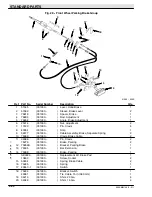
Page 74: ...STANDARD PARTS 550E MM149 5 01 6 4 Fig 2 Replacement Brushes 1 ...

Page 75: ...ARTS 6 5 550E MM149 10 10 02575 ALL Fig 2 Replacement Brushes Ref Part No Serial Number Description Qty 1 75718 001330 Brush Polypropylene 2 1 75722 001330 Brush Abrasive Bristle 2 12876 001330 Brush Kit Repair 2 ...

Page 76: ...1330 Bracket Resistor Mounting 1 4 75236 001330 Frame Tractor 1 5 75812 001330 Decal Stripe 1 6 75813 001330 Decal Stripe R H 1 7 75814 001330 Decal Stripe L H 1 8 76150 001330 Decal Warning High Voltage 1 9 31684 001330 Shroud Front 1 10 75379 1 001330 004362 Wrap Steering L H Replaced by none 1 11 25186 001330 Housing Steering Column 1 12 27474 001330 Oval TENNANT 1 13 75379 001330 004362 Wrap S...

Page 77: ...l Warning High Voltage 1 38 75418 001330 Gasket Control Panel Side 2 39 75417 001330 Gasket Control Panel 2 40 32514 001330 Decal Caution Charging 1 41 39697 001330 Seal Foam 2 42 42834 1 001330 Seal Foam 2 43 76068 001330 Decal Battery Requirements 1 44 76073 001330 Decal Charging Instructions 1 45 75316 1 001330 Box Control Panel 1 46 76118 001330 Decal 72 V 1 47 75243 001330 Panel Back 1 48 760...

Page 78: ...1330 Sleeve 4 7 51459 001330 Adjuster Seat 1 8 51458 001330 Adjuster Assembly Seat 1 9 52615 001330 Spacer Seat Adjuster 4 10 16669 001330 Plate Seat Mount 1 11 75272 001330 Hinge Seat 1 12 50836 001330 Switch Micro 1 13 75386 001330 Rod Seat Spring 1 14 26103 001330 Pin Roll 1 15 75390 001330 Bracket Seat Spring 1 16 45261 001330 Spring 1 17 44307 001330 Bumper Rubber 2 18 06526 001408 Cage Coil ...

Page 79: ...50E Ref Part No Serial Number Description Qty 1 75439 001330 Insulation Side Panel 1 2 75435 001330 Insulation Dash Panel 1 3 75433 001330 Insulation Side Kick Panel 1 4 76868 001330 Insulation Side Access Door 1 5 75434 001330 Insulation Back Panel 1 6 76867 001330 Insulation Top Access Door 1 ...

Page 80: ...ll 2 6 75247 001330 Link Control 1 7 51304 1 001330 Bearing 2 8 75275 001330 Spacer Bearing 2 9 75297 001330 Pin Roll 2 10 75292 001330 Cam 2 11 75281 001330 Cam 1 12 75280 001330 Cam 1 13 32490 001330 Washer 2 o 14 76171 001330 Wire Kit Foot Control 1 Y 15 75289 001330 Stud 2 Y 16 12259 001330 Switch 4 Y 17 75263 001330 Bracket L 2 18 76736 001330 Clamp Cable 1 19 75264 001330 Shaft Control 1 20 ...

Page 81: ...75634 001330 Deflector Assembly Scrub Brush 1 Y 8 75642 001330 Bearing Sleeve 2 Y 9 75636 001330 Sleeve 2 Y 10 75681 001330 Bearing 4 Y 11 75638 001330 Deflector Scrub Brush 1 Y 12 75649 001330 Skirt Deflector 1 Y 13 75648 001330 Retainer Deflector Skirt 1 14 75643 001330 Sleeve 2 15 22297 001330 Clamp Worm Drive 2 16 50845 001330 Hose Hopper 1 o 75569 001330 Hopper Assembly 1 Y 17 75571 001330 Re...

Page 82: ...10 001330 Screw Hex 1 o 75790 001330 Squeegee Assembly Right Side 1 Y 8 75791 001330 Door Squeegee 1 Y 9 59617 001330 Flap Containment 1 Y 10 75788 001330 Frame Side Squeegee R H 1 Y 11 75799 001330 Strip Backup 1 Y 12 60015 001330 Blade Squeegee 1 Y 13 75588 001330 Bracket Bridge 1 Y 14 75592 001330 Band Squeegee Retaining 1 Y 15 87579 001330 Latch Cam Lock Band 1 Y 16 75528 001330 Pin Door Locki...

Page 83: ...Door 1 6 32486 001330 Washer 1 7 39810 001330 Screw Hex 1 o 75795 001330 Squeegee Assembly L H 1 Y 8 75796 001330 Door Squeegee L H 1 Y 9 59617 001330 Flap Containment 1 Y 10 75789 001330 Frame Side Squeegee L H 1 Y 11 75799 001330 Strip Backup 1 Y 12 60015 001330 Blade Squeegee 1 Y 13 75588 001330 Bracket Bridge 1 Y 14 75592 001330 Band Squeegee Retaining 1 Y 15 87579 001330 Latch Band 1 Y 16 114...

Page 84: ...STANDARD PARTS 550E MM149 10 10 6 14 Fig 10 Scrub Head Lift Group 4 5 8 9 10 11 12 13 14 15 16 17 15 18 19 20 20 19 21 22 23 24 25 26 27 28 29 15 31 30 31 30 16 9 8 32 33 27 34 6 7 2 1 3 ...

Page 85: ...eeve 1 13 02589 001339 Nut 1 14 75627 001330 Lift Scrub Head 1 15 11716 001330 Fitting Grease 45_ 4 16 11048 001330 Fitting Grease 2 17 75622 001330 Stud 1 18 77097 001330 Fitting Elbow 1 19 39348 001330 Washer 3 20 42120 9 001330 Bearing 2 21 75617 001330 Spring 1 22 40846 001330 Spring 1 23 75766 001330 Plate Mounting 1 24 75764 001330 Plate 1 25 75616 001330 Shaft Pivot 1 26 34359 001330 Fittin...

Page 86: ...STANDARD PARTS 550E MM149 5 01 6 16 Fig 11 Scrub Head Solution Supply and Control Group 2 6 8 1 3 4 5 7 24 28 27 7 9 10 16 24 13 15 14 17 12 11 19 18 20 22 23 18 19 18 21 25 26 24 28 27 24 ...

Page 87: ... 12072 004039 Arm Control 1 11 14877 001330 Elbow 1 12 12052 001330 004038 Valve Replacement Kit Water 1 12 12060 004039 Valve Water 1 13 75601A 001330 Tube Connector 1 14 42133A 001330 Tee Plastic 1 15 75611 001330 Plug Flushing 1 16 75803 001330 004038 Plate Valve Mounting 1 16 12074 004039 Plate Valve Mounting 1 17 75802 1 001330 Bracket Water Valve Mounting 1 18 50544 001330 Clamp Cable 3 19 4...

Page 88: ...ANDARD PARTS 550E MM149 5 01 6 18 Fig 12 Scrub Head Front Brush Drive Components Group 2 3 4 5 6 7 8 9 10 1 11 12 13 14 15 16 17 18 19 20 21 22 23 24 25 26 27 28 29 30 31 32 33 34 35 36 37 38 39 40 41 5 4 ...

Page 89: ... Arm Front Brush Drive 1 18 51938 001330 Plug Thread 1 19 14834 001330 Plug Oil Check 1 20 75578 001330 Sprocket Brush Drive 1 79599 001330 Screw Set 2 21 00927 001330 Key Square 1 22 75696 001330 Gasket Front Chain Cover 1 23 75692 1 001330 Cover Chain Housing 1 24 75671 001330 Cover Oil Fill 1 25 75672 001330 Gasket Oil Fill Cover 1 o 26 75750 001330 Chain Assembly Front 1 Y 75579 001330 Link Ch...

Page 90: ... 7 75600 001330 Shim Bearing Bracket 0 12 3 mm 3 76218 001330 Shim Bearing Bracket 0 06 1 5 mm 1 8 42498 001330 Bracket Bearing R H 1 9 75760 001330 Channel Bearing Cover 1 o 75656 001330 Idler Assembly Front Scrub Brush 1 Y 10 40390 001330 Cover Grease Fitting 1 Y 11 51564 001330 Washer 1 Y 12 51046 001330 Ring Retaining 1 Y 13 41032 001330 Bearing 1 Y 14 40076 001330 Shield Bearing 1 Yo 15 40999...

Page 91: ...Y 4 75655 001330 Arm Rear Brush Idler 1 Yo 5 40999A 001330 Plug Brush Idler 1 YY 6 02984 001330 Screw Socket 2 Y 7 40076 001330 Shield Bearing 1 Y 8 41032 001330 Bearing 1 Y 9 51046 001330 Ring Retaining 1 Y 10 51564 001330 Washer 1 Y 36328 001330 Washer Belleville 1 o 75761 001330 Shaft Assembly Brush 1 Y 11 75781 001330 Hub Brush 1 Y 12 51317 001330 Pin Roll 1 13 42639 001330 Bracket Bearing 1 1...

Page 92: ...ARD PARTS 550E MM149 8 02 6 22 Fig 15 Scrub Head Rear Brush Drive Components Group 2 3 4 5 6 7 8 9 10 1 11 12 13 14 15 16 17 18 19 20 21 22 23 24 25 26 27 28 29 30 31 32 33 34 35 36 37 38 39 40 41 42 4 5 43 ...

Page 93: ...0 Arm Rear Brush Drive 1 20 07316 15 001330 Breather Chain Case 1 21 75577 001330 Sprocket Motor Drive 1 79598 001330 Screw Set 2 22 00915 001330 Key Square 1 o 23 75749 001330 Chain Assembly Rear 1 Y 75579 001330 Link Chain Connecting 1 24 75672 001330 Gasket Oil Fill Cover 1 25 75671 001330 Cover Oil Fill 1 26 75680 1 001330 Cover Chain Housing 1 27 75669 001330 Gasket Rear Chain Cover 1 28 0092...

Page 94: ...STANDARD PARTS 550E MM149 5 01 6 24 Fig 16 Vacuum Fan Assembly 2 3 4 5 6 7 8 9 10 1 11 12 13 14 15 16 17 18 19 20 21 22 23 24 26 27 28 29 30 31 32 33 34 35 7 8 22 23 26 26 26 32 36 37 35 38 25 ...

Page 95: ... 1 Y 17 75456 001330 Shim 0 003 in 0 07 mm 1 Y 17 75456 1 001330 Shim 0 005 in 0 12 mm 1 Y 17 75456 2 001330 Shim 0 010 in 0 25 mm 2 Y 17 75456 3 001330 Shim 0 020 in 0 50 mm 2 Y 17 75456 4 001330 Shim 0 060 in 1 52 mm 2 Y 18 15331 004738 Washer Special 1 Y 19 61693 004738 Nut Slotted Hex 1 Y 20 03745 001330 004737 Sheave Fan 1 Y 20 375615 004738 Sheave Fan 1 21 378996 001330 V Belt 1 22 40565 001...

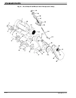
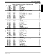
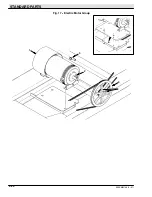
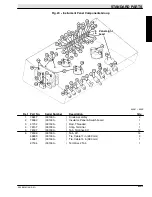
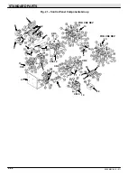
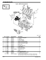
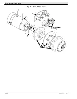
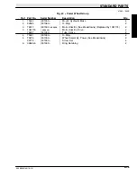
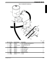
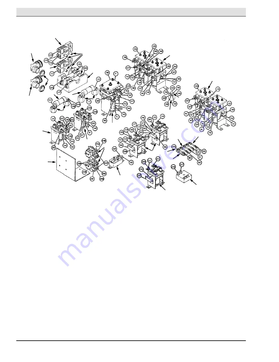
Page 96: ...STANDARD PARTS 550E MM149 5 01 6 26 Fig 17 Electric Motor Group 1 2 3 4 5 6 ...

Page 97: ...1330 001407 Motor See Breakdowns Replaced by 03463 1 1 03462 001408 Motor Electric See Breakdowns 1 2 00935 001330 Key Square 1 3 SK2612 001330 004299 Sheave Replacement Kit 1 3 391801 004300 Sheave Motor 1 4 39332 001330 Screw Set 2 5 02076 001330 Cover Terminal 2 6 03464 001408 xxxxxx Bracket Motor Mounting Replaced by none 1 ...

Page 98: ...STANDARD PARTS 550E MM149 5 01 6 28 Fig 18 Steering Column Group 17 18 2 3 4 5 6 7 8 9 10 1 11 12 13 14 15 16 19 20 21 22 20 ...

Page 99: ...late 1 Y 8 14700 1 001330 Ferrule Insulation 1 Y 9 14700 2 001330 Spring 1 Y 10 14700 3 001330 Washer 1 11 17269 001330 Wheel Steering 1 12 57676 001330 Nut 1 13 75326 001330 Column Steering 1 14 44310 001330 Sleeve 2 15 10829 001330 Screw Cap 2 16 57982 001330 005268 Control Steering See Breakdowns 1 16 74176 005269 005607 Control Steering See Breakdowns 1 17 56690 001330 005607 Fitting Straight ...

Page 100: ...01330 Ammeter 1 5 63255 001330 Voltmeter 1 6 76120 001330 Decal Battery 1 7 76121 001330 Label Brush Switch 1 8 76031 001330 Circuit Breaker 1 9 76234 001330 Decal Squeegee 1 10 76306 001330 Switch Toggle 1 11 76123 001330 Decal Console 1 12 56992 001330 Plugbutton 5 13 44828 001330 Switch Pushbutton 1 o 14 09334 001330 Switch Ignition 1 Y 09336 001330 Key Ignition 1 15 76131 001330 Switch Pushbut...

Page 101: ...rial Number Description Qty 1 76247 001330 Diode Assembly 2 2 76062 001330 Insulator Panel Switchboard 1 3 41702 001330 Rod Threaded 1 4 76107 001330 Strip Terminal 1 5 76187 001330 Tab Terminal 90_ 12 6 76186 001330 Tab 45_ 14 49263 001330 Tie Cable 11 in 280 mm 3 44961 001330 Tie Cable 15 in 380 mm 1 27184 001330 Terminal 2 Tab 1 ...

Page 102: ...STANDARD PARTS 550E MM149 5 01 6 32 Fig 21 Control Panel Components Group 1 2 1 3 3 4 5 6 7 8 9 10 11 11 11 12 13 14 8 13 15 16 17 18 19 20 21 22 8 CR1 CR4 CR5 CR9 CR15 CR3 FOR CR2 REV FOR CR8 REV ...

Page 103: ...8 Relay 1 11 76092 001330 Relay 150 A 1 SPDT 4 12 76095 001330 Relay 100 A 1 DPDT 1 13 76096 001330 Relay 100 A 2 SPDT 2 14 41702 001330 Rod Threaded 1 15 49047 001330 Relay Time Delay 1 16 44662 001330 Insulator Fuse Block 1 17 14141 001330 Block Fuse 1 18 14346 001330 Strip Terminal 2 19 07423 001330 Fuse 15 A 5 20 21666 001330 005484 Replacement Kit 2 20 87284 005485 Relay 2 21 76227 001330 Bra...

Page 104: ...76129 001330 Resistor 20 K Ohm 5 Watt 1 Y 6 76130 001330 Resistor 250 Ohm 20 Watt 1 Y 7 14141 001330 Block Fuse 1 Y 8 44662 001330 Insulator Fuse Block 1 Y 9 25532 001330 Diode Silicon 3 Y 10 75313 001330 Bracket Mounting 1 Y 11 14347 001330 Strip Short Terminal 1 Y 12 21666 001330 005484 Replacement Kit 2 Y 12 87284 005485 Relay 2 Y 13 21725 005585 Wire Kit MFR Control 1 Y 49266 001330 Tie Cable ...

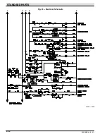
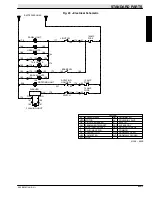
Page 105: ...STANDARD PARTS 6 35 550E MM149 5 01 Fig 23 Electrical Schematic 1 2 3 4 5 01228 550E ...

Page 106: ...STANDARD PARTS 550E MM149 5 01 6 36 Fig 23 Electrical Schematic 1 2 3 4 5 01228 550E ...

Page 107: ... PERMANENT MAGNET CIRCUIT BREAKER MOTOR POWER RELAY VM PB P J PM CB M MTR BATTERIES LINES SWITCH FLASHING LIGHT 160 161 22 171 144 167 168 176 BLK BRN RED FLASHER 172 15 AMP FUSE 15 AMP FUSE 23 179 153 ROTATING LIGHT SW 207 ROTATING LIGHT 206 169 BRAKE SW 163 BRAKE LIGHTS 173 158 155 159 TAIL LIGHTS 156 157 154 174 164 HEAD LIGHTS 165 165 15 AMP FUSE 21 170 143 LIGHT SW 177 PANEL LIGHT 159 156 175...

Page 108: ...STANDARD PARTS 550E MM149 5 01 6 38 Fig 24 Power Wheel Group 2 3 4 5 6 1 5 Hydraulic Brake Assembly ...

Page 109: ...330 Mount Hydraulic Brake 2 2 02585 001363 O Ring 2 3 76017 001330 xxxxxx Motor Electric See Breakdowns Replaced by 1061174 2 3 1061174 xxxxxx Motor Electric Drive 2 76207 001330 Tube Splice 8 4 75341 001330 O Ring 2 5 75274 001330 Wheel Assembly Power See Breakdowns 2 39772 001330 Screw Set 4 6 09663 6 001330 Ring Retaining 2 ...

Page 110: ...STANDARD PARTS 550E MM149 5 01 6 40 Fig 25 Electrical Wire Harness Group 1 2 3 4 5 6 7 8 9 10 11 12 13 ...

Page 111: ...4 001330 Connector 6 Plug 1 8 76169 001330 Harness Wire 1 9 76168 001330 Harness Wire Right Drive Motor 1 10 76167 001330 Harness Wire Left Drive Motor 1 11 31652 001330 Harness Wire Tractor Auto Squeegee 1 12 76231 001330 Harness Wire Tank Section Auto Squeegee 1 76172 001330 Wire Kit Instrument Panel Includes Loose Wires 4 5 12 13 14 15 24 25 52 69 70 73 74 77 78 108 1 76174 001330 Wire Kit Cont...

Page 112: ...y o 75286 001330 004506 Tire Assembly Front Replaced by 48893 2 Y 1 75360 001330 004506 Rim Tire 1 Y 2 75365 001330 004506 Valve Tire 1 Y 3 75346 001330 004506 Tire Replaced by 48893 1 4 24339 001330 Nut Wheel 18 o 48889 004507 Tire Assembly Front 2 Y 5 75360 004507 Rim Tire 1 Y 6 75365 004507 Valve Tire 1 Y 7 48888 004507 Tire 1 ...

Page 113: ... Pin Clevis 1 7 14330 001330 Clevis Adjustable 1 8 52163 001330 Rod Brake Push 1 o 9 64950 001330 Brake Cylinder Master 1 Y 374240 001330 Cap Cyl Assy Master Brake 1 10 48126 001330 Plug 1 11 53078 001330 Elbow 1 12 76058 001330 Tube Brake Line 1 13 46236 001330 Clamp Tube 4 14 76059 001330 Tube Brake Line 2 15 06843 001330 Tube Brake Line R H 2 16 76087 001330 Fitting Plug 4 17 06844 001330 Tube ...

Page 114: ... 10120 001330 Pin Clevis 4 8 40354 001330 Strip 1 9 32477 001330 Cable Assembly Brake Separate Spring 2 10 75369 001330 Clevis Brake Cable 2 11 09088 001330 Pin Clevis 2 o 75276 001330 Brake Parking 2 Y 12 75269A 001330 Bracket Parking Brake 1 Y 13 75535 001330 Bar Extension 1 Y 14 75368 001330 Brake Parking 1 Y SK2223 001330 Replacement Kit Brake Pad 1 Y 10830 001330 Screw Socket 2 15 50304 00133...

Page 115: ...kdowns 1 2 19207 001330 Decal Hydraulic Oil Fluid 1 3 SK2612 001330 004299 Sheave Replacement Kit 1 3 25661 004300 Sheave 1 4 52402 001330 Fitting Straight 1 5 11399 001330 Clamp Worm Drive 1 6 75396 001330 Bracket Mounting 1 7 40565 001330 Screw Shoulder 2 8 40840 001330 Bushing Bronze 2 9 75283 001330 Bracket Mounting 1 10 75389 001330 004299 V belt 1 10 378968 004300 V belt 1 ...

Page 116: ... Part No Serial Number Description Qty 1 31623 001330 Bracket Valve Mounting 1 2 31574 001330 Valve Hydraulic Solenoid See Breakdowns 1 3 56690 001330 Fitting Straight 1 4 47504 001330 Fitting Elbow 1 5 47522 001330 Fitting Elbow 45_ 1 6 55685 001330 Fitting Straight 3 7 16456 001330 Fitting Restrictor 1 ...

Page 117: ...STANDARD PARTS 6 47 550E MM149 5 01 Fig 31 Hydraulic Schematic 001330 005607 02361 550E ...

Page 118: ...STANDARD PARTS 550E MM149 5 01 6 48 Fig 32 Hydraulic Schematic 005608 11118 550E ...

Page 119: ...0E Ref Part No Serial Number Description Qty 1 31572 001330 Fitting Straight 1 o 2 55619 001330 Filter Assembly Hydraulic 1 Y 3 55740 001330 Element Hydraulic Filter 1 4 53076 001330 Fitting Elbow 1 5 51779 001330 Fitting Tee 1 6 31573 001330 Fitting Straight 1 7 42215 005608 Fitting Tee 1 ...

Page 120: ...E MM149 5 01 6 50 Fig 34 Hydraulic Hoses Group 001330 005607 2 3 5 6 7 8 9 1 Squeegee Lift Cylinder Steering Cylinder Filter Power Steering Head Lift Cylinder Head And Squeegee Lift Valve Accessory Pump And Reservoir 8 4 ...

Page 121: ...30 005607 Hose Hydraulic 1 2 31566 001330 005607 Hose Hydraulic 1 3 31672 001330 005607 Sleeve Hydraulic Hose 1 4 31563 001330 005607 Hose Hydraulic 1 5 31558 001330 005607 Hose Hydraulic 1 6 02549 001330 005607 Hose Hydraulic 1 7 31568 001330 005607 Hose Hydraulic 1 8 31565 001330 005607 Hose Hydraulic 2 9 31570 001330 005607 Hose Hydraulic 2 ...

Page 122: ...6 52 Fig 35 Hydraulic Hoses Group 005608 E P R T L IN C2 C1 OUT OUT IN 2 3 4 5 6 7 8 9 1 Steering Cylinder Filter Power Steering Head Lift Cylinder Head And Squeegee Lift Valve Accessory Pump And Reservoir 8 Squeegee Lift Cylinder 10 ...

Page 123: ...1 31567 005608 Hose Hydraulic 1 2 31566 005608 Hose Hydraulic 1 3 31672 005608 Sleeve Hydraulic Hose 1 4 35486 005608 Hose Hydraulic 1 5 31558 005608 Hose Hydraulic 1 6 02549 005608 Hose Hydraulic 1 7 31568 005608 Hose Hydraulic 1 8 31565 005608 Hose Hydraulic 2 9 31570 005608 Hose Hydraulic 2 10 57288 005608 Hose Hydraulic 1 ...

Page 124: ...STANDARD PARTS 550E MM149 10 10 6 54 Fig 36 Trunnion Group 1 2 3 4 5 6 7 8 9 10 11 12 13 14 15 16 17 18 19 20 21 22 14 23 23 24 25 26 27 28 29 30 Tractor Frame Trailer Frame 22 26 27 31 ...

Page 125: ... 41082 001330 O ring 1 Y 13 41083 001330 Bearing Liner 1 Y 14 41084 001330 Bearing Thrust 2 Y 15 32724 001330 Housing Pivot 1 Y 16 41081 001330 Washer 1 Y 17 41074 001330 Washer Lock 1 Y 18 06845 001405 Washer Spacer 1 Y 19 15331 001405 Washer 1 Y 20 08099 001405 Screw Hex 1 21 75375 001330 Wrap Hose 2 49263 001330 Tie Cable 11 in 280 mm 4 22 39912 001330 Screw Hex 2 23 56820 001330 Fitting Elbow ...

Page 126: ...50E MM149 5 01 6 56 Fig 37 Solution and Recovery Tanks Group Front Side 14 15 16 17 15 17 2 3 4 5 6 7 8 9 10 1 11 12 13 18 19 20 21 22 23 24 25 26 27 28 29 30 31 32 33 34 35 36 37 38 39 14 18 19 31 32 33 34 10 1 28 29 ...

Page 127: ...3 Washer Cleanout Door Retaining 2 Y 16 06333 001330 001410 Service Kit Cleanout Door 1 Y 17 42034 001411 004933 Door Cleanout 1 Y 18 06332 001411 004933 Gasket Door 1 19 28165 001330 004344 Fastener Nut 4 19 25663 004345 004933 Fastener Nut 4 20 63511 001330 Plug 2 21 75045 001330 Tube Front Suction 1 22 76532 001330 Seal Suction Tube 1 23 22297 001330 Clamp Worm Drive 1 24 75635AM 001330 Hose As...

Page 128: ...DARD PARTS 550E MM149 5 01 6 58 Fig 38 Solution and Recovery Tanks Group Rear Side Solution Tank To Rear Squeegee 2 3 4 5 6 7 8 9 10 1 11 12 13 14 15 16 17 18 19 20 21 22 23 24 25 26 27 28 29 30 31 32 11 13 ...

Page 129: ...001330 Clamp Worm Drive 2 14 25649 001330 Hose Rear Squeegee Suction 1 o 78819 001330 004933 Cover Assembly Recovery Tank Cleanout 1 Y 15 25665 001330 004344 Replacement Kit Thumbscrew 4 Y 15 25656 004345 004933 Fastener Thumbscrew 4 Y 16 06224 001330 001410 Service Kit Cleanout Door 1 Y 17 06228 001411 004933 Door Cleanout 1 Y 18 26015 001330 004933 Fastener Washer 4 Y 19 06227 003697 004933 Gask...

Page 130: ...nd Wheel Assembly Rear Replaced by 48894 2 Y 1 78189 001330 004506 Rim Tire 1 Y 2 75365 001330 004506 Valve Tire Air 1 Y 3 75346 001330 004506 Tire Replaced by 48894 1 4 05928 001330 xxxxxx Cap Hub 2 5 24339 001330 Nut Wheel 12 o 48891 004507 Tire and Wheel Assembly Rear 2 Y 6 78189 004507 Rim Tire 1 Y 7 75365 004507 Valve Tire Air 1 Y 8 48888 004507 Tire 1 ...

Page 131: ... Description Qty 1 51545 001330 Lever Brake 1 2 76816 001330 Spacer Brake 1 3 51562 001330 Sleeve 2 4 76903 001330 Rod Adjustment 1 5 10120 001330 Pin Clevis 3 6 76904 001330 Angle Brake Adjustment 1 7 40354 001330 Strip 1 8 42132 1 001330 Cable Assembly 2 9 33620 001330 Bracket Cable Mount 1 10 33622 001330 Decal Instruction Parking Brake 1 ...

Page 132: ...2 5 33619 001330 001404 Disc Brake 2 6 33618 001330 001404 Spacer Brake Disc 12 7 33617 001330 Hub Wheel 2 8 32126 001330 Stud 6 9 75073 001330 Bearing Assembly 2 10 75072 5 001330 Seal Wheel Hub 2 11 75075 001330 Bearing Assembly 2 12 57567 001330 Cap Dust 2 13 41112 001330 Nut Slotted Hex 2 14 31705 001330 Washer 2 15 75269A 001405 Bracket Parking Brake 2 16 04210 001405 Shim 20 Ga 8 17 04048 00...

Page 133: ...8673 001330 Guard L H 1 2 75136 1 001330 004933 Bumper Rear L H 1 2 61259 004934 Bumper Rear L H 1 3 75132 001330 Plate Bumper 1 4 75136 001330 004933 Bumper Rear R H 1 4 61260 004934 Bumper Rear R H 1 5 78670 001330 Guard R H 1 6 78059 001330 004933 Bracket Mounting 2 6 61261 004934 Bracket Mounting 2 7 75190 001330 Guard Squeegee 2 ...

Page 134: ...09874 550E Ref Part No Serial Number Description Qty o 32415 001330 Rear Squeegee Assembly 1 Y 1 78096 001330 Arm L H 1 Y 2 76922 1 001330 Plate Pivot 1 Y 3 76921 001330 Adjuster Rear 1 Y 4 76927 001330 Pivot Adjuster 1 Y 5 78641 001330 Screw Thumb 2 Y 6 59639A 001330 Guide Spring 2 Y 7 32985 001330 Nut 2 Y 8 32493 001330 Washer Flat 12 Y 9 76979 001330 Washer Thrust 12 Y 10 76392 001330 Sleeve Be...

Page 135: ...160 xxxxxx 001446 Mount Kit Caster 1 Y 29 10149 001447 Mount Caster 2 Y 30 76390 001330 Sleeve 6 Y 31 76391 001330 Link 2 32 76353 001330 Bolt Eye 2 33 47745 001330 Spring 2 34 78093 001330 Rod 1 20021 001330 Pin Roll 1 35 78695 001330 Strip Spring 2 36 51530 001330 Pin Clevis 1 37 08175 001330 Pin Cotter 4 38 48884 001330 Adaptor Cylinder 1 39 76340 001330 Switch Roller 1 40 76269 001330 Bracket ...

Page 136: ...001450 Cylinder Hydraulic 1 58 51534 001330 Pin Clevis 1 59 55586 001330 Fitting Straight 1 60 77097 001330 Fitting Elbow 1 61 54041 001330 Pin Roll 1 62 76997 001330 001449 Adapter Cylinder Rod 1 62 09626 001450 Adapter Cylinder Rod 1 63 36328 001330 Washer Belleville 3 64 51564 001330 Washer 7 65 78560 001330 Blade Front Squeegee Urethane 1 66 78561 001330 Blade Rear Squeegee Urethane 1 ...

Page 137: ...2 Fig 2 SRS Control Panel Assembly 7 5 Fig 3 SRS Front Side of Solution Tank Group 001330 004933 7 6 Fig 4 SRS Front Side of Solution Tank Group 004934 7 8 Fig 5 SRS Rear Side of Solution Tank Group 001330 004933 7 10 Fig 6 SRS Rear Side of Solution Tank Group 004934 7 12 Fig 7 SRS Wire Harnesses 7 14 ...

Page 138: ...16 17 14 15 16 17 2 3 4 5 6 7 8 9 11 12 13 18 19 20 21 22 23 19 25 26 27 28 29 30 31 32 33 34 35 36 37 38 41 43 44 45 46 47 48 49 50 59 58 57 47 55 54 53 52 51 To Detergent Tank 1 56 6 24 24 24 24 24 24 19 24 24 19 19 19 19 19 19 19 24 26 25 31 32 37 33 34 34 32 32 36 35 37 23 39 40 42 ...

Page 139: ... 79495 001330 Bracket Mounting 1 22 16485 001330 007294 Pump Metering See Breakdowns Replaced by 9006876 1 22 1057970 007295 Pump Assy Water W Connector 1 23 75604 001330 Elbow 2 24 11399 001330 Clamp Worm Drive 10 25 47846 3 001330 Hose 49 in 1250 mm 2 26 44031 001330 Clamp Hose 6 27 47846 001330 Hose 2 28 75119 001330 Tee 1 29 62595 5 001330 Molding Cover Pump 1 30 79445 001330 Cover Pump 1 31 7...

Page 140: ...60 004039 Valve Water 1 49 29035 001330 Connector Nipple 1 50 23563 001330 Elbow 1 51 11442 7 001330 Connector Nipple 1 52 07484 001330 Coupling 1 53 11870 001330 Elbow 45_ 1 54 11442 8 001330 Connector 1 55 79606 001330 Nozzle Spray 1 56 26565 001330 Knob 1 57 75802 1 001330 Bracket Water Valve Mounting 1 58 79301 001330 Strainer Suction 1 59 75501B 001330 Frame Scrub Head 1 ...

Page 141: ...9318 001330 Control Panel Assembly 1 Y 1 79314 001330 Console Instrument 1 Y 2 32798 001330 Panel Front 1 Y 3 63837 001330 Switch Cleaning Solution Metering 1 Y 4 16440 001330 Resistor 1 Y 5 07422 001330 Holder Fuse 1 Y 45595 001330 Fuse 10 A 1 Y 6 79410 001330 Decal Control Panel 1 Y 7 63814 001330 Knob 1 8 47178 4 001330 Plugbutton 2 ...

Page 142: ...550E MM149 12 05 7 6 Fig 3 SRS Front Side of Solution Tank Group 001330 004933 1 2 3 4 5 6 6 7 8 8 9 10 11 13 14 15 26 16 17 18 19 20 21 23 24 25 26 26 26 27 27 27 28 29 30 30 32 33 29 29 34 34 35 35 36 12 22 31 ...

Page 143: ...015 001330 004933 Fastener 4 16 75635AM 001330 004933 Hose Assy W 1cuff 1 5d 120l 1 5 1 17 11531 001330 004933 Clamp Worm Drive 1 18 76426 001330 004933 Washer Sealing 4 19 61157 001330 004933 Tube Suction Front 1 20 76532 001330 004933 Gasket Suction Tube Front 1 o 78819 001330 004933 Door Assembly Cleanout 1 Y 21 25665 001330 004344 Thumbscrew Replacement Kit 4 Y 21 25656 004345 004933 Fastner T...

Page 144: ...RTS 550E MM149 12 05 7 8 Fig 4 SRS Front Side of Solution Tank Group 004934 2 3 4 5 6 7 8 9 10 1 11 12 13 14 15 16 17 18 19 20 21 22 23 24 25 26 27 28 29 30 31 32 33 27 27 27 11 31 28 25 25 25 13 14 15 32 6 8 ...

Page 145: ...6 004934 Door 2 14 61174 004934 Gasket Door 2 15 61175 004934 Plate Door 2 16 75635AM 004934 Hose Assy W 1cuff 1 5d 120l 1 5 1 17 11531 004934 Clamp Worm Drive 1 18 76426 004934 Washer Rubber Seal 4 19 61157 004934 Tube Front Suction 1 20 76532 004934 Gasket Suction Tube Front 1 21 61171 004934 Stud Door Latch 4 22 61170 004934 Rod Door Latch 4 23 36644 004934 Nut Locking 4 24 61181 004934 Pivot D...

Page 146: ...2 3 4 5 6 15 16 17 18 19 20 21 22 23 24 25 26 27 28 29 30 31 32 33 34 35 37 38 39 40 41 14 20 38 To Detergent Pump 11 9 10 8 7 36 12 13 41 03347 550E Ref Part No Serial Number Description Qty 1 79453 001330 004933 Plate 1 2 375724 001330 004933 Cap Filler 1 3 375724 001348 004933 Cap Filler 1 ...

Page 147: ... Spray Rubber 1 22 23498 001330 004933 Clamp Worm Drive 1 23 76426 001330 004933 Washer Rubber Seal 6 24 79545 001330 004933 Seal Suction Tube 1 25 79471 001330 004933 Tube Rear Squeegee Suction 1 26 43555 001330 004933 Clamp Worm Drive 2 27 25649 001330 004933 Hose Rear Squeegee Suction 1 o 78819 001330 004933 Door Assembly Cleanout 2 Y 28 06224 001330 001410 Service Kit Cleanout Door 1 Y 29 0622...

Page 148: ...SRS PARTS 550E MM149 12 05 7 12 Fig 6 SRS Rear Side of Solution Tank Group 004934 2 4 5 6 7 8 9 10 1 11 12 13 14 15 16 17 18 19 20 21 22 23 24 25 26 27 28 29 30 31 32 3 To Detergent Pump 24 30 17 2 ...

Page 149: ...34 Nut Stainless Steel 8 18 61181 004934 Pivot Door Hinge 4 19 79500 004934 Deflector Spray Rubber 1 20 23498 004934 Clamp Worm Drive 1 21 76426 004934 Washer Rubber Seal 6 22 79545 004934 Seal Suction Tube 1 23 79471 004934 Tube Rear Squeegee Suction 1 24 43555 004934 Clamp Worm Drive 2 25 25649 004934 Hose Rear Squeegee Suction 1 o 79477 004934 Filter Assembly Laminar Flow L H 1 Y 26 79473 1 004...

Page 150: ...SRS PARTS 550E MM149 12 05 7 14 Fig 7 SRS Wire Harnesses 1 01105 550E Ref Part No Serial Number Description Qty 1 76370 001330 Wire Harness Control Box 1 ...

Page 151: ...Kit 8 7 Fig 7 Fire Extinguisher Kit 8 7 Fig 8 Operating Light Kit 8 8 Fig 9 SRS Operating Light Kit 8 8 Fig 10 SRS Operating Light Kit 8 9 Fig 11 Squeegee Wand Kit 8 10 Fig 12 SRS Squeegee Wand Kit 8 12 Fig 13 Mirror Kit 8 14 Fig 14 Tire and Wheel Group Foam Filled 8 14 Fig 15 Dust Shield Kit 8 15 Fig 16 Battery Chargers 8 15 Fig 17 Batteries 8 15 Fig 18 Batteries International 8 15 Fig 19 Side Sq...

Page 152: ... 3 4 5 1 00317 ALL Ref Part No Serial Number Description Qty o 75903 001330 Guard Kit Overhead 1 Y 1 76862 001330 Guard Top 1 Y 2 76858 001330 Leg Front R H 1 Y 3 76859 001330 Leg Front L H 1 Y 4 76860 001330 Leg Rear R H 1 Y 5 76861 001330 Leg Rear L H 1 ...

Page 153: ...unting 1 Y 3 33783 001330 U Bolt 2 Y 4 09384 001330 Clamp Cable 5 Y 10701 001330 Switch Toggle 1 Y 07423 001330 Fuse 15 A 1 Y 47164 001330 Decal 15 A Label 1 Y 76037 001330 Wire Kit Includes Wires 153 205 207 1 Y 5 46314 001330 Grommet 1 Y 45223 001330 Terminal Quick disconnect 4 Y 45224 001330 Terminal Quick disconnect 2 o 44683 1 001330 Light Revolving Amber 1 Y 44681 1 001330 Lens Light Amber 1...

Page 154: ... 550E Ref Part No Serial Number Description Qty o 75906 001330 Bumper Kit Heavy Duty 1 Y 1 75108 001330 Bumper Solution and Recovery Tank 2 Y 2 78101 001330 Bumper Tractor L H 1 Y 3 78099 001330 Bumper Tractor R H 1 Y 4 75673 001330 Bumper Scrub Head 2 Y 5 75144 001330 Bracket 2 ...

Page 155: ... Serial Number Description Qty o 79426 001330 Bumper Kit Heavy Duty 1 Y 1 75673 001330 Bumper Scrubber Head 2 Y 2 76880 001330 Bumper Solution and Recovery Tank L H 1 Y 3 76881 001330 Bumper Solution and Recovery Tank R H 1 Y 4 78101 001330 Bumper Tractor L H 1 Y 5 78099 001330 Bumper Tractor R H 1 ...

Page 156: ...al Tool 4 2 1 3 00338 ALL Ref Part No Serial Number Description Qty o 79518 001330 Tool Assembly Sludge Removal 1 Y 1 03292B 001330 Grip Handle 1 Y 2 79517 001330 Handle Sludge Removal 1 Y 3 79515 001330 Squeegee 1 Y 4 79508 1 001330 Retainer Squeegee 1 ...

Page 157: ...ution Tank 1 Y 1 76075 001330 Tee Barbed 1 Y 2 76076 001330 Valve Water 1 Y 3 11399 001330 Clamp Worm Drive 2 Fig 7 Fire Extinguisher Kit 1 00830 ALL Ref Part No Serial Number Description Qty o 78127 001330 Extinguisher Kit Fire 1 Y 1 25312 001330 Extinguisher Fire 1 NOTE To identify parts shown but not listed here see Section 6 Standard Parts ...

Page 158: ... Terminal 1 Y 76187 001330 004933 Tab Terminal 1 Y 09385 001330 004933 Clamp Cable 1 Y 10632 19 001330 004933 Grommet 2 in I D 50 mm 1 550E Fig 9 SRS Operating Light Kit 001330 004933 Ref Part No Serial Number Description Qty o 79440 001330 004933 Light Kit Operating SRS 1 Y 45365 001330 004933 Lamp Assembly Headlight 2 Yo 45389 001330 004933 Light Assembly Panel 1 YY 45390 001330 004933 Bulb 1 Y ...

Page 159: ...1 Y 76035 004934 007059 Wire Kit Includes Wires 143 165 166 169 177 178 1 Y 76186 004934 007059 Tab Terminal 1 Y 76187 004934 007059 Tab Terminal 1 550E Fig 11 Operating Light Kit 007060 Ref Part No Serial Number Description Qty o 9001910 007060 Light Kit Hd Tl Ci 550e 1 Y 45635 007060 Housing Rep Bysk1924 2 Yo 45389 007060 Light Panl 36vdc Clr 28v Lamp 1 YY 45390 007060 Bulb 1 Y 10701 007060 Swit...

Page 160: ... 2 95 8 10 Fig 12 Squeegee Wand Kit Solution Tank Recovery Tank Engine Cover 2 3 4 5 6 7 8 9 10 1 11 12 13 14 15 16 17 18 19 19 16 13 4 18 18 NOTE To identify parts shown but not listed here see Section 6 Standard Parts ...

Page 161: ...queegee 1 Y 11 76154A 001330 Tube Suction 1 Y 12 75076 001330 Gasket Rear Suction Tube 1 Y 13 03823 001330 Clamp Toggle 4 Y 14 76152 001330 Adapter Kit Suction Tube 1 Y 15 76153 001330 Adapter Squeegee Wand 1 Y 16 75095 001330 Gasket Suction Tube 2 Y 17 75127 001330 Hose and Cuff Assembly 1 Y 18 76426 001330 Washer Sealing 11 Y 19 391839 001330 Clip Finger Grip 2 Y 76192 001330 Wire Kit Includes W...

Page 162: ...E MM149 12 05 8 12 Fig 13 SRS Squeegee Wand Kit 2 3 4 5 6 7 8 9 10 11 12 13 14 15 16 17 18 19 1 Solution Tank Solution Tank 20 3 19 21 NOTE To identify parts shown but not listed here see Section 6 Standard Parts ...

Page 163: ... 1 Y 9 75127 001330 Hose and Cuff Assembly 1 Y 10 14432 001330 Clamp 1 Y 11 79535 001330 Adaptor Wand Hose 1 Y 12 79547 001330 Bracket Squeegee Wand Storage 1 Y 13 79538 001330 Adaptor Tank 1 Y 14 03823 001330 Clamp 1 Y 15 75128 001330 Spindle Adjusting 1 Y 16 79546 001330 Gasket 1 Y 17 40171 001330 Handle Extension 1 Y 18 79532 001330 Adaptor Squeegee Wand 1 Y 19 391839 001330 Clip Finger Grip 2 ...

Page 164: ...156 001330 Mirror Kit 1 Y 1 76863 001330 Mirror Rear View 1 NOTE To identify parts shown but not listed here see Section 6 Standard Parts 550E Fig 15 Tire and Wheel Kit Foam Filled Ref Part No Serial Number Description Qty 48890 001330 Tire Assy Foam 8 75 16 5 9 5bc 9bolt 2 48892 001330 Tire Assy Foam 8 75 16 5 45psi 2 ...

Page 165: ...26 001330 Connector Gray 350 A 2 o 75912 001330 Charger Battery 36 V Gould 1 Y 22892 001330 Connector Gray 175 A 2 o 398290 001330 Charger Battery 36 V Mac 1 Y 22892 001330 Connector Gray 175 A 2 550E Fig 18 Batteries Ref Part No Serial Number Description Qty o 76028 001330 Battery 36 V 510 Ah Exide 2 Y 22892 001330 Connector Gray 175 A 1 o 76020 001330 Battery 36 V 840 Ah Exide 2 Y 22892 001330 C...

Page 166: ...rial Number Description Qty o 04595 001330 Extension Kit Side Squeegees 1 Y 1 04598 001330 Frame Side Squeegee R H 1 Y 2 03395 001330 Blade Squeegee 4 Y 3 03409 001330 Strip Backup 4 Y 4 03408 001330 Retainer Blade 4 Y 04597 001330 Frame Side Squeegee L H 1 NOTE To identify parts shown but not listed here see Section 6 Standard Parts ...

Page 167: ...8 17 550E MM149 10 10 Fig 21 Documentation Group 550E Ref Part No Serial Number Description Qty MM149 000000 Manual Pkg 550E 1 9004761 000000 Manual Cd Rom Oprtr Parts All NA 1 10392 000000 Video Operator 550 1 ...

Page 168: ...OPTIONS 550E MM149 9 99 8 18 ...

Page 169: ...wn 74176 9 7 Fig 7 Hydraulic Steering Valve Breakdown 65242 9 8 Fig 8 Hydraulic Solenoid Control Valve Breakdown 31574 9 9 Fig 9 Hydraulic Cylinder Breakdown 04431 9 10 Fig 10 Electric Drive Motor Breakdown 76213 9 11 Fig 11 Electric Drive Motor Breakdown 76214 9 11 Fig 12 Electric Motor Breakdown 16450 9 11 Fig 13 Electric Motor Breakdown 03462 9 11 Fig 14 Electric Motor Breakdown 76017 9 12 Fig ...

Page 170: ...5 Motor Bracket 3 00112 ALL Ref Part No Serial Number Description Qty o 16485 000000 Pump Metering Solution 1 Y 1 63923 000000 Connector Kit Tubing 1 Y 2 63922 000000 Valve Kit Pump 1 Y 3 63921 000000 Replacement Kit Bellows 1 Y 4 63924 000000 Motor Gear 1 Y 5 02430 000000 Crank Replacement Kit 1 ...

Page 171: ... 12 05 Fig 2 SRS Solution Pump Breakdown 79326 1 1 2 2 2 2 2 2 2 05092 550E Ref Part No Serial Number Description Qty o 79326 1 000000 Pump Solution 1 Y 1 63925 000000 Housing Pump 1 Y 2 19960 000000 Repair Kit Solution Pump 1 ...

Page 172: ...1 75338 000000 Spline Power Wheel 1 Y 2 37656 000000 Stud 9 Y 3 02529 000000 Hub Kit 1 Y 4 02528 000000 Bearing And Seal Kit 1 Y 30140 000000 Seal 1 Y 5 02470 000000 Gear Kit 1 Y 6 37655 000000 O Ring 1 Y 7 372896 000000 Cover Large 603915 1 Y 8 75259 000000 Disc Brake 1 Y 9 75271 000000 Sleeve Brake Disc 6 Y 10 38941 000000 Cover Small 14 02 039 005 1 Y 11 372895 000000 Plunger 610801 1 ...

Page 173: ...5 1 1 1 1 2 5 02363 550E Ref Part No Serial Number Description Qty o 76043 000000 Pump Hydraulic 1 Y 1 SK2201 000000 Seal Kit 1 Y 2 02409 000000 Control Valve Kit 1 Y 3 02407 000000 Pressure Plate Kit 1 Y 4 02408 000000 Cartridge Kit 1 Y 5 02410 000000 Shaft And Bearing Kit 1 ...

Page 174: ...ew 7 Y 2 38873 000000 Cover Cap 1 Y 3 57156 000000 Geroter 1 Y 4 74094 000000 Spacer Plate 1 Y 5 58596 000000 Drive 1 Y 6 74218 000000 Pin 1 Y 7 74109 000000 Race Bearing 2 Y 8 74110 000000 Bearing Needle 1 Y 9 74112 000000 Bushing Seal 1 Y 10 74111 000000 Ring Retainer 1 Y 11 74186 000000 Retainer Chk 1 Y 12 74187 000000 Ball 1 Y 13 74188 000000 Seat Chk Ball 1 Y 14 74189 000000 Screw Set 1 Y 15 ...

Page 175: ...crew 7 Y 2 74181 000000 Cap End 1 Y 3 57156 000000 Geroter 1 Y 4 74182 000000 Plate Wear 1 Y 5 58596 000000 Drive 1 Y 6 74218 000000 Pin 1 Y 7 74109 000000 Race Bearing 2 Y 8 74110 000000 Bearing Needle 1 Y 9 74112 000000 Bushing Seal 1 Y 10 74111 000000 Ring Retainer 1 Y 11 74186 000000 Retainer Chk 1 Y 12 74187 000000 Ball 1 Y 13 74188 000000 Seat Chk Ball 1 Y 14 74189 000000 Screw Set 1 Y 15 74...

Page 176: ... No Serial Number Description Qty o 65242 000000 Steer Control Hyd 4 04 5 1300 1 Y 1 74174 000000 Cap Screw 7 Y 2 74194 000000 Cap End 1 Y 3 65235 000000 Geroter 1 Y 4 74182 000000 Plate Wear 1 Y 5 58596 000000 Drive 1 Y 6 74218 000000 Pin 1 Y 7 74109 000000 Race Bearing 2 Y 8 74110 000000 Bearing Needle 1 Y 9 74112 000000 Bushing Seal 1 Y 10 74111 000000 Ring Retainer 1 Y 11 74190 000000 Seal Kit...

Page 177: ... No Serial Number Description Qty o 31574 000000 Valve Hydraulic Solenoid 1 Y 1 04198 000000 Seal Kit 1 Y 2 31642 000000 Inlet Section 1 Y 3 31643 000000 Valve Section 1 Y 4 02542 000000 Coil 36 V 2 Y 5 02520 000000 Valve Section Manual 1 Y 6 02519 000000 Handle Assembly Complete 1 Y 7 04525 000000 Nut Solenoid 2 Y 8 04185 000000 Linkage Kit Handle 1 ...

Page 178: ...9 10 Fig 9 Hydraulic Cylinder Breakdown 04431 2 3 1 3 03175 ALL Ref Part No Serial Number Description Qty o 04431 000000 Cylinder Hydraulic 1 Y 1 47801 000000 Fitting Grease 1 Y 2 04499 000000 Bearing 1 Y 3 04477 000000 Seal Kit 1 ...

Page 179: ...ption Qty o 76214 000000 Motor Electric Rear 1 Y 02524 000000 Brush 4 Y 02525 000000 Brush Spring 4 Y 76205 000000 Harness Wire 1 Y 76207 000000 Tube Splice 2 550E Fig 12 Electric Motor Breakdown 16450 Ref Part No Serial Number Description Qty o 16450 000000 Motor Electric replaced by 03463 1 Y 02526 000000 Brush 8 Y 02525 000000 Brush Spring 8 Y 79103 000000 Rocker Arm 1 550E Fig 13 Electric Moto...

Page 180: ...0 Brush 8 Y 02525 000000 Brush Spring 8 550E Fig 15 Electric Relay Breakdown 76095 Ref Part No Serial Number Description Qty 76095 000000 Relay 1 SK2220 000000 Contact Kit F 76095 Replmt Rep by76095 1 550E Fig 16 Electric Relay Breakdown 76096 Ref Part No Serial Number Description Qty 76096 000000 Relay 1 SK2218 000000 Replacement Kit Contacts Replaced by None 1 ...

Page 181: ...BREAKDOWNS 9 13 550E MM149 10 10 Fig 17 Electric Relay Breakdown 76092 1 1 1 00997 550E Ref Part No Serial Number Description Qty o 76092 000000 Relay 1 Y 1 SK2219 000000 Replacement Kit Contacts 1 ...

Page 182: ...BREAKDOWNS 550E MM149 10 10 9 14 ...

Page 183: ...CROSS REFERENCE 10 1 550E MM149 10 10 SECTION 10 CONTENTS PAGE PART NUMBER TO PAGE NUMBER CROSS REFERENCE LIST 10 2 PART DESCRIPTION TO PAGE NUMBER CROSS REFERENCE LIST 10 8 ...

Page 184: ...4477 9 10 04499 9 10 04525 9 9 04595 8 16 04597 8 16 04598 8 16 04733 12 6 15 05928 6 60 06222 7 11 06223 6 2 6 3 7 11 06224 6 59 7 7 7 11 06227 6 59 7 7 7 11 06228 6 59 7 7 7 11 06229 6 2 6 3 7 7 06230 7 7 06231 7 7 06279 6 15 06332 6 2 6 3 6 57 06333 6 57 06334 9 11 06418 6 20 6 21 6 55 06474A 6 10 06526 6 8 06573 6 19 6 23 06837 6 55 06843 6 43 06844 6 43 06845 6 55 06846 6 55 07259 6 55 07316 ...

Page 185: ...718 1 6 23 30140 9 4 30145 7 7 31313 6 17 31554 6 15 6 66 31558 6 51 6 53 31563 6 51 31565 6 51 6 53 31566 6 51 6 53 31567 6 51 6 53 31568 6 51 6 53 31570 6 51 6 53 31572 6 49 31573 6 49 31574 6 46 9 9 31615 6 25 31623 6 46 31642 9 9 31643 9 9 31652 6 41 31672 6 51 6 53 31684 6 6 31705 6 62 32126 6 62 32376 6 23 32415 6 64 32477 6 44 32486 6 12 6 13 32490 6 10 32492 6 65 32493 6 10 6 19 6 23 6 64 ...

Page 186: ...8 8 8 9 45375 8 8 8 9 45389 8 8 8 9 45390 8 8 8 9 45405 7 3 45595 7 5 45635 8 9 46236 6 43 46314 8 3 46800 6 11 47010 1 6 29 47010 2 6 29 47010 3 6 29 47010 4 6 29 47010 6 6 29 47010 7 6 29 47164 6 33 8 3 8 8 8 9 47178 13 6 30 47178 4 7 5 47504 6 46 47522 6 46 47745 6 65 47801 6 25 9 10 47845 6 17 47846 3 7 3 47846 6 17 7 3 47848 7 3 48126 6 43 48183 6 7 48252 8 9 48884 6 65 48888 6 42 6 60 48889 ...

Page 187: ...74187 9 6 9 7 74188 9 6 9 7 74189 9 6 9 7 74190 9 7 9 8 74194 9 8 74195 9 6 9 7 9 8 74218 9 6 9 7 9 8 74251 9 6 9 7 9 8 75045 6 57 75049 6 64 75050 6 65 75054 8 11 8 13 75072 5 6 62 75073 6 62 75075 6 62 75076 6 2 6 3 6 59 8 11 75081A 6 59 75095 8 11 75096 6 59 75098 6 59 75103 6 57 75106 6 57 75108 8 4 75118 8 11 8 13 75119 6 17 7 3 75127 8 11 8 13 75128 8 11 8 13 75132 6 63 75136 1 6 63 75136 6 ...

Page 188: ...75750 6 19 75757 6 12 6 13 75760 6 19 6 20 75761 6 20 6 21 75764 6 15 75766 6 15 75768 6 19 6 23 75769 6 19 75772 6 23 75773 6 19 75774 6 23 75780 6 19 6 23 75781 6 20 6 21 75786 6 19 6 23 75788 6 12 75789 6 13 75790 6 12 75791 6 12 75795 6 13 75796 6 13 75799 6 2 6 3 6 12 6 13 75801 6 17 7 3 75802 1 6 17 7 4 75803 6 17 7 3 75811 6 6 75812 6 6 75813 6 6 75814 6 6 75815 6 59 75816 6 57 75903 8 2 75...

Page 189: ... 6 65 76997 6 66 77097 6 15 6 66 78059 6 63 78078 6 15 78080 6 43 78093 6 65 78096 6 64 78099 8 4 8 5 78101 8 4 8 5 78118 6 7 78127 8 7 78156 8 14 78189 6 60 78398 7 3 78560 6 66 78561 6 66 78562 6 12 6 13 78641 6 64 78642 6 65 78670 6 63 78673 6 63 78695 6 65 78795 6 65 78802 6 2 6 3 78819 6 59 7 7 7 11 79103 9 11 79273 2 7 3 79273 4 7 3 79273 7 3 79300 7 3 79301 6 11 7 4 79314 7 5 79318 7 5 7932...

Page 190: ...acket Centering Spring 6 10 Bracket Door Hinge 6 59 Bracket Hinge L H 7 11 Bracket Hinge R H 7 11 Bracket Hose 6 7 Bracket L 6 10 Bracket Motor Mounting Replaced by none 6 27 Bracket Mounting 6 19 6 25 6 34 6 45 6 63 6 65 7 3 Bracket Parking Brake 6 44 6 62 Bracket Relay Mounting 6 33 Bracket Resistor Mounting 6 6 Bracket Seat Spring 6 8 Bracket Squeegee Wand Mount 8 13 Bracket Squeegee Wand Stora...

Page 191: ...H 6 6 Decal Stripe 6 6 Decal Valve Panel 6 7 Decal Wand Instruction 8 11 Decal Wand 8 11 8 13 Decal Warning High Voltage 6 6 6 7 Decal Warning Use Scrubber 6 12 Deflector Assembly Brush L H 6 13 Deflector Assembly Brush 6 12 Deflector Assembly Scrub Brush 6 11 Deflector Scrub Brush 6 11 Deflector Spray Rubber 7 7 7 11 7 13 Deflector Top Sandblast 7 9 Deflector 6 20 Diode Assembly 6 31 Diode Silico...

Page 192: ... 7 7 7 9 Hose Kit Vacuum SRSr 6 2 Hose 180 in 4570 mm 7 3 Hose 2 in 50 mm 7 3 Hose 29 in 740 mm 7 3 Hose 4 in 100 mm 7 3 Hose 48 in 1213 mm 7 3 Hose 49 in 1250 mm 7 3 Hose 6 in 150 mm 7 3 Hose Flex Vacuum 3 0d 20 0l 6 3 Hose Flex Vacuum 4 0d 41 1l 6 3 Hose Flex Vacuum 4 0d 54 0l 6 3 Hose Hopper 6 2 6 11 Hose Hydraulic 6 51 6 53 Hose Rbr 2 00id 2 40od 07 5l 6 3 Hose Rear Squeegee Suction 6 59 7 11 ...

Page 193: ...ormance Package 400 Hour 6 2 Pin Articulating Locking 6 55 Pin Clevis 6 10 6 11 6 15 6 19 6 23 6 43 6 44 6 61 6 62 6 65 6 66 7 11 Pin Cotter 6 15 6 19 6 23 6 55 6 65 Pin Door Locking 6 12 6 13 Pin Roll 6 8 6 10 6 12 6 13 6 15 6 20 6 21 6 43 6 65 6 66 Pin 9 6 9 7 9 8 Pivot Adjuster 6 64 Pivot Door Hinge 6 57 6 59 7 9 7 13 Pivot Headlock 6 15 Pivot Shaft 6 55 Plate Bumper 6 63 Plate Door 6 57 6 59 7...

Page 194: ...trol Lever Assembly 7 3 Spacer Plate 9 6 Spacer Bearing 6 10 Spacer Brake Disc 6 62 Spacer Brake 6 44 6 61 Spacer Isolator 6 23 Spacer Motor 6 19 6 23 Spacer Seat Adjuster 6 8 Spacer Spring 6 23 Spacer Switch 7 3 Spacer 6 25 8 11 9 6 9 7 Spindle Adjusting 8 13 Spindle 8 11 Spline Power Wheel 9 4 Spring Kit Scu 9 8 Spring Kit Scu 9 6 9 7 Spring Brake Cable 6 44 Spring Brush 9 11 Spring Centering 6 ...

Page 195: ...6 55 6 64 Washer Lock 6 55 Washer Nylon 6 17 Washer Rubber Seal 7 11 Washer Rubber Located Inside Tank 6 59 Washer Sealing 6 57 7 7 8 11 8 13 Washer Spacer 6 55 Washer Special 6 25 Washer Thrust 6 64 Washer Wavy 6 25 Washer 6 10 6 12 6 13 6 15 6 19 6 20 6 21 6 23 6 29 6 55 6 62 6 65 6 66 7 3 Wheel Assembly Power See Breakdowns 6 39 Wheel Steering 6 29 Wire Harness Control Box 7 14 Wire Kit Auto Sq...

Page 196: ...CROSS REFERENCE 550E MM149 10 10 10 14 ...

Page 197: ...ave regarding our machine manuals If you find an error or have a suggestion please complete this postage paid form and mail it to us Thank you for helping us make zero defects a way of life at Tennant Manual No Rev No Publish Date Page Machine Report Error Suggestion Name Date Customer Number Company Address City State Zip Code ...

Page 198: ...GE NECESSARY IF MAILED IN THE UNITED SATES BUSINESS REPLY MAIL FIRST CLASS MAIL PERMIT NO 94 MINNEAPOLIS MN POSTAGE WILL BE PAID BY ADDRESSEE Technical Publications 15 701 North Lilac Drive P O Box 1452 Minneapolis MN 55440 9947 TENNANT COMPANY ...

Page 199: ...ave regarding our machine manuals If you find an error or have a suggestion please complete this postage paid form and mail it to us Thank you for helping us make zero defects a way of life at Tennant Manual No Rev No Publish Date Page Machine Report Error Suggestion Name Date Customer Number Company Address City State Zip Code ...

Page 200: ...GE NECESSARY IF MAILED IN THE UNITED SATES BUSINESS REPLY MAIL FIRST CLASS MAIL PERMIT NO 94 MINNEAPOLIS MN POSTAGE WILL BE PAID BY ADDRESSEE Technical Publications 15 701 North Lilac Drive P O Box 1452 Minneapolis MN 55440 9947 TENNANT COMPANY ...

Reviews: