OPERATION
550E MM149 (8--02)
2-8
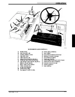
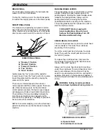
DRAIN TANK LAMP (OPTION)
The drain tank lamp is present on machines
equipped with the drain tank option. The lamp
lights when the recovery tank is nearly full. The
machine operator can then plan to return to a
dumping station.
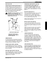
SQUEEGEE POSITION LAMP
The squeegee position lamp lights when the rear
squeegee is either fully raised or lowered. This
can be helpful to the operator when the squeegee
is not visible.
HOUR METER
The hour meter is located on the control panel.
The meter records the number of hours the
machine is operated and is useful in determining
when to perform periodic maintenance procedures
which are listed in the maintenance chart.
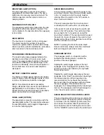
SCRUB BRUSH PRESSURE GAUGE
The scrub brush pressure gauge indicates the
electrical current flow to the rear scrub brush
motor. The gauge needle should be in the green
zone when scrubbing. If the needle stays in the
red zone continuously, the scrub brush pattern or
floor contact area is excessive and should be
decreased.
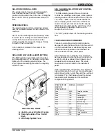
BATTERY CONDITION GAUGE
The battery condition gauge indicates the battery
state of charge. When the gauge needle is in the
red zone, the batteries should be recharged.
NOTE: If machine stalls due to low battery
charge, disconnect the vacuum fan belt and wait
approximately 5 to 10 minutes. The batteries
should then have recovered enough to be able to
power the machine to a charger station.
PANEL LAMP (OPTION)
The panel lamp is present on machines with the
operating lights option. The lamp lights whenever
the operating lights switch toggle is flipped up to
turn on the operating lights.
SCRUB BRUSH SWITCH
The scrub brush switch controls the power to the
scrub brush motors. Place the scrub brush switch
in the “on” position to start the scrub brushes
rotating. Place the switch in the “off” position to
stop scrub brush rotation.
The switch also provides the circuit electrical
overload protection with a 30 A circuit breaker.
In the event of a circuit overload, the switch will
return to the “off” position. The switch must then
be returned to the “on” position to restart the
scrub brush rotation. If the overload which caused
the switch to trip is still present, the switch circuit
breaker will continue to stop electrical current flow
until the overload is corrected.
NOTE: To prolong the life of the scrub brush
motors and chains, always raise the scrub head
before turning on brush drive motors.
SQUEEGEE SWITCH
The squeegee switch, in conjunction with a
hydraulic flow sensing device, controls the
position of the rear squeegee.
Flipping the switch toggle up places the rear
squeegee in the “Squeegee Up” position. This
position cannot be overridden by the hydraulic
flow sensing device.
Flipping the switch toggle down places the rear
squeegee in the “Down” position when traveling in
the forward direction. When traveling in the
reverse direction, the hydraulic flow sensing
device overrides the squeegee switch and raises
the rear squeegee. This prevents the rear
squeegees from being damaged when traveling in
reverse. The squeegee switch should always be
in the “Down” position when scrubbing.
SCRUB HEAD POSITION CONTROL LEVER
The scrub head position control lever controls the
position of the scrub head lift cylinder. Pulling the
control lever into the “RAISE” position raises the
scrub head. The middle “HOLD” position stops
scrub head movement. Pushing the control lever
into the “LOWER” position lowers the scrub head.
Summary of Contents for 550
Page 10: ...GENERAL INFORMATION 550E MM149 3 94 viii ...
Page 12: ...OPERATION 550E MM149 3 91 2 2 ...
Page 30: ...OPERATION 550E MM149 9 00 2 20 ...
Page 32: ...MAINTENANCE 550E MM149 3 91 3 2 ...
Page 62: ...MAINTENANCE 550E MM149 2 05 3 32 ...
Page 66: ...APPENDIX 550E MM149 3 91 4 4 ...
Page 74: ...STANDARD PARTS 550E MM149 5 01 6 4 Fig 2 Replacement Brushes 1 ...
Page 96: ...STANDARD PARTS 550E MM149 5 01 6 26 Fig 17 Electric Motor Group 1 2 3 4 5 6 ...
Page 105: ...STANDARD PARTS 6 35 550E MM149 5 01 Fig 23 Electrical Schematic 1 2 3 4 5 01228 550E ...
Page 106: ...STANDARD PARTS 550E MM149 5 01 6 36 Fig 23 Electrical Schematic 1 2 3 4 5 01228 550E ...
Page 117: ...STANDARD PARTS 6 47 550E MM149 5 01 Fig 31 Hydraulic Schematic 001330 005607 02361 550E ...
Page 118: ...STANDARD PARTS 550E MM149 5 01 6 48 Fig 32 Hydraulic Schematic 005608 11118 550E ...
Page 168: ...OPTIONS 550E MM149 9 99 8 18 ...
Page 182: ...BREAKDOWNS 550E MM149 10 10 9 14 ...

