MAINTENANCE
550E MM149 (3--91)
3-8
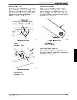
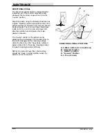
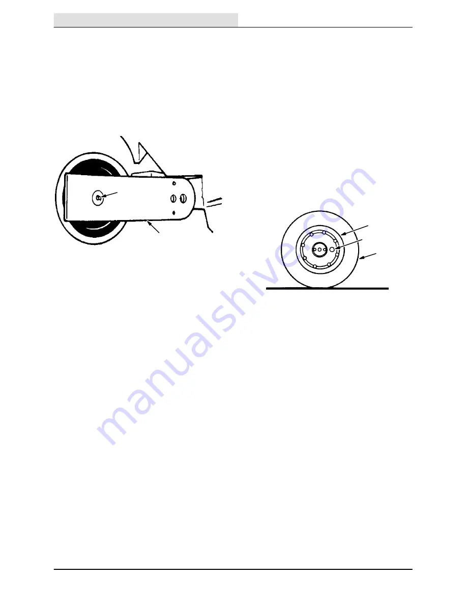
SCRUB BRUSH IDLER PLUGS
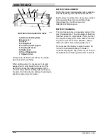
There are two grease fittings which are used to
lubricate the scrub brush idler plugs. The grease
fittings are located in the center of each idler plug
and are covered with plastic caps. Snap the caps
open to apply grease to the fittings. Use
Lubriplate EMB grease (TENNANT Part No.
01433--1). Wipe off all excess grease and replace
the plastic cap. Apply grease to the fittings after
every 50 hours of operation.
A
B
03793
BRUSH IDLER PLUG
A. Idler Arm
B. Grease Fitting
REAR WHEELS
The rear wheels have automotive-type bearings.
Repack the bearings with automotive type wheel
bearing grease after every 2000 hours of
operation.
SCRUB BRUSH DRIVE CHAINS
Each scrub brush is driven by a chain assembly.
Each chain case should be filled with SAE 30
engine oil to the oil level plug. Add oil through the
round cover at the top of the case. Check the oil
level after every 50 hours of operation.
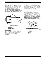
POWER WHEEL
The power wheel is a gear reduction unit used to
drive the machine. Each front wheel is equipped
with its own power wheel that is driven by an
electric motor. The power wheels are lubricated
with SAE 90 mild to extreme pressure lubricant.
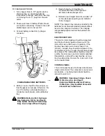
When the fill plug is in the three o’clock position,
add lubricant until it seeps out of the fill hole.
Check the lubricant level after every 200 hours of
operation.
A
B
C
01149
POWER WHEEL
A. Power Wheel
B. Fill Plug
C. Tire
Summary of Contents for 550
Page 10: ...GENERAL INFORMATION 550E MM149 3 94 viii ...
Page 12: ...OPERATION 550E MM149 3 91 2 2 ...
Page 30: ...OPERATION 550E MM149 9 00 2 20 ...
Page 32: ...MAINTENANCE 550E MM149 3 91 3 2 ...
Page 62: ...MAINTENANCE 550E MM149 2 05 3 32 ...
Page 66: ...APPENDIX 550E MM149 3 91 4 4 ...
Page 74: ...STANDARD PARTS 550E MM149 5 01 6 4 Fig 2 Replacement Brushes 1 ...
Page 96: ...STANDARD PARTS 550E MM149 5 01 6 26 Fig 17 Electric Motor Group 1 2 3 4 5 6 ...
Page 105: ...STANDARD PARTS 6 35 550E MM149 5 01 Fig 23 Electrical Schematic 1 2 3 4 5 01228 550E ...
Page 106: ...STANDARD PARTS 550E MM149 5 01 6 36 Fig 23 Electrical Schematic 1 2 3 4 5 01228 550E ...
Page 117: ...STANDARD PARTS 6 47 550E MM149 5 01 Fig 31 Hydraulic Schematic 001330 005607 02361 550E ...
Page 118: ...STANDARD PARTS 550E MM149 5 01 6 48 Fig 32 Hydraulic Schematic 005608 11118 550E ...
Page 168: ...OPTIONS 550E MM149 9 99 8 18 ...
Page 182: ...BREAKDOWNS 550E MM149 10 10 9 14 ...

