MAINTENANCE
550E MM149 (10--10)
3-10
HYDRAULIC FLUID FILTER
Replace the filter element after every 1200 hours
of operation. Check the hydraulic fluid level and
refill as needed.
TO REPLACE HYDRAULIC FLUID FILTER
ELEMENT
1. Park the machine on a smooth, level
surface, stop the motor, and set the machine
parking brake.
FOR SAFETY: Before Leaving Or
Servicing Machine; Stop On Level
Surface, Set Parking Brake, Turn Off
Machine And Remove Key.
2. Raise the access cover and side door.
3. Unthread and discard the hydraulic fluid filter
elements.
NOTE: Discard all hydraulic fluid drained from the
system. Drained hydraulic fluid may contain
foreign material harmful to the hydraulic system.
4. Apply a thin coat of hydraulic fluid to the seal
of the new hydraulic fluid filter element.
5. Thread and hand tighten the new hydraulic
fluid filter elements on the filter heads.
6. Operate the machine and check for leaks.
Correct any leaks found.
7. Check the hydraulic fluid reservoir level and
fill as required.
8. Close the access cover and side door.
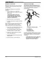
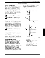
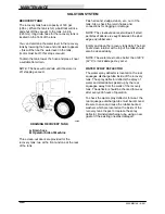
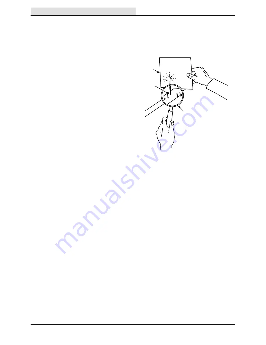
HYDRAULIC FLUID LEAKS
Hydraulic fluid escaping at high pressure from a
very small hole can be almost invisible, and can
cause serious injuries. Use a piece of cardboard
or wood, rather than hands, to search for
suspected leaks.
A
C
B
00002
HYDRAULIC PIN HOLE LEAK
A. Cardboard
B. Pin Hole Leak
C. Magnifying Glass
If injured by escaping hydraulic fluid, see a doctor
at once. Serious infection or reaction can develop
if proper medical treatment is not administered
immediately.
FOR SAFETY: When Servicing Machine;
Use Cardboard To Locate Leaking
Hydraulic Fluid Under Pressure.
Summary of Contents for 550
Page 10: ...GENERAL INFORMATION 550E MM149 3 94 viii ...
Page 12: ...OPERATION 550E MM149 3 91 2 2 ...
Page 30: ...OPERATION 550E MM149 9 00 2 20 ...
Page 32: ...MAINTENANCE 550E MM149 3 91 3 2 ...
Page 62: ...MAINTENANCE 550E MM149 2 05 3 32 ...
Page 66: ...APPENDIX 550E MM149 3 91 4 4 ...
Page 74: ...STANDARD PARTS 550E MM149 5 01 6 4 Fig 2 Replacement Brushes 1 ...
Page 96: ...STANDARD PARTS 550E MM149 5 01 6 26 Fig 17 Electric Motor Group 1 2 3 4 5 6 ...
Page 105: ...STANDARD PARTS 6 35 550E MM149 5 01 Fig 23 Electrical Schematic 1 2 3 4 5 01228 550E ...
Page 106: ...STANDARD PARTS 550E MM149 5 01 6 36 Fig 23 Electrical Schematic 1 2 3 4 5 01228 550E ...
Page 117: ...STANDARD PARTS 6 47 550E MM149 5 01 Fig 31 Hydraulic Schematic 001330 005607 02361 550E ...
Page 118: ...STANDARD PARTS 550E MM149 5 01 6 48 Fig 32 Hydraulic Schematic 005608 11118 550E ...
Page 168: ...OPTIONS 550E MM149 9 99 8 18 ...
Page 182: ...BREAKDOWNS 550E MM149 10 10 9 14 ...

