MAINTENANCE
550E MM149 (6--96)
3-12
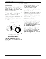
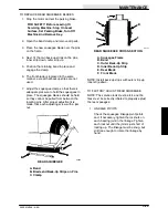
A
B
C
D E
F
G
H
I
01148
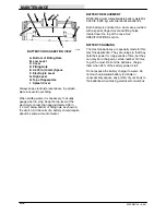
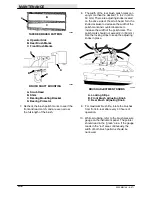
BATTERY CROSS-SECTION VIEW
A. Bottom of Filling Hole
B. Low Level
C. Cover
D. Filling Hole
E. 0.375 in (10 mm) Space
F. Electrolyte Level
G. High Level
H. Top of Separators
I. Splash Cover
Always keep electrolyte level above the splash
plate, but avoid over-filling.
When adding water, it is necessary to visually
gauge when to stop. Keep the top level of the
electrolyte no less than approximately 0.38 in
(10 mm) below bottom of filling hole as shown in
the sketch. All the cells of a battery should require
about the same amount of water.
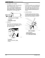
BATTERY REPLACEMENT
NOTE: Maximum total allowable battery weight is
5,300 lb (2405 kg) with two identical batteries.
Each battery is enclosed in a steel case provided
with a special hinged cover and lifting holes
located near the top of the case. See
SPECIFICATIONS
section.
BATTERY CHARGING
The machine batteries are specially made for this
machine application. They are unique in that they
hold their power for long periods of time, but they
can only be recharged a certain number of times.
To get the most life from the batteries, charge
them when 25% of the battery power is left.
Do not expose the battery charger to water. Do
not touch uninsulated battery terminals or
unnecessarily expose any portion of your body to
the batteries when making electrical connections.
Summary of Contents for 550
Page 10: ...GENERAL INFORMATION 550E MM149 3 94 viii ...
Page 12: ...OPERATION 550E MM149 3 91 2 2 ...
Page 30: ...OPERATION 550E MM149 9 00 2 20 ...
Page 32: ...MAINTENANCE 550E MM149 3 91 3 2 ...
Page 62: ...MAINTENANCE 550E MM149 2 05 3 32 ...
Page 66: ...APPENDIX 550E MM149 3 91 4 4 ...
Page 74: ...STANDARD PARTS 550E MM149 5 01 6 4 Fig 2 Replacement Brushes 1 ...
Page 96: ...STANDARD PARTS 550E MM149 5 01 6 26 Fig 17 Electric Motor Group 1 2 3 4 5 6 ...
Page 105: ...STANDARD PARTS 6 35 550E MM149 5 01 Fig 23 Electrical Schematic 1 2 3 4 5 01228 550E ...
Page 106: ...STANDARD PARTS 550E MM149 5 01 6 36 Fig 23 Electrical Schematic 1 2 3 4 5 01228 550E ...
Page 117: ...STANDARD PARTS 6 47 550E MM149 5 01 Fig 31 Hydraulic Schematic 001330 005607 02361 550E ...
Page 118: ...STANDARD PARTS 550E MM149 5 01 6 48 Fig 32 Hydraulic Schematic 005608 11118 550E ...
Page 168: ...OPTIONS 550E MM149 9 99 8 18 ...
Page 182: ...BREAKDOWNS 550E MM149 10 10 9 14 ...

