MAINTENANCE
3-13
550E MM149 (6--96)
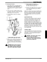
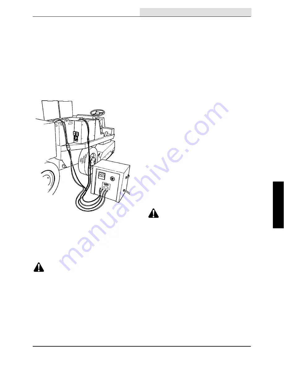
TO CHARGE BATTERIES
1. Turn charger timer to “off” position before
disconnecting or connecting batteries
receptacles to charger, and before inserting
or removing the “A.C.” plug from the wall
outlet.
2. Check water level in battery. Water should
cover plates completely. If water is low, add
distilled water, but do not over-fill.
3. Connect battery connectors to charger
connector.
01146
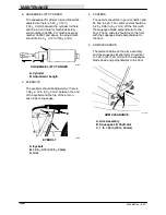
CHARGING MACHINE BATTERIES
4. Battery covers should be braced open, so
that the gases can escape. Otherwise, the
top of the battery eventually develops a
conductive leak between cells and battery
tray.
WARNING: Batteries Emit Hydrogen
Gas. Explosion Or Fire Can Result.
Keep Sparks And Open Flame Away.
Keep Covers Open When Charging.
5. Begin charge by turning timer to
recommended hours. Pilot light and
ammeter indicate charger is on.
6. Batteries are charged when timer reads “off”
or the electrolyte specific gravity indicates
100% charged.
NOTE: The charger may remain connected to the
batteries for occasional extended periods without
harm to the charger or batteries. The charging
rate gradually tapers down as the batteries are
recharged.
ELECTRIC MOTORS
The electric motor brushes should be inspected
and the brush dust should be blown out of the
motor after every 200 hours of operation. If the
brushes have been worn to less than 0.75 in
(20 mm) in length, they should be replaced. If the
commutator is worn or rough, the armature should
be removed. The commutator should be turned in
a lathe, the mica recut, and commutator polished.
Reassemble, and seat the new brushes, using a
brush seating stone. Be sure the rocker arm is set
on the neutral mark.
CONTROL PANEL
The control panel houses the forward and reverse
relays and controls. The components are not user
serviceable -- only trained personnel should be
allowed to work on it.
WARNING: Hazardous Voltage. Shock
Or Electrocution Can Result.
Disconnect Batteries Before Working
On Machine. Only Qualified Personnel
Should Work Inside Panel.
Summary of Contents for 550
Page 10: ...GENERAL INFORMATION 550E MM149 3 94 viii ...
Page 12: ...OPERATION 550E MM149 3 91 2 2 ...
Page 30: ...OPERATION 550E MM149 9 00 2 20 ...
Page 32: ...MAINTENANCE 550E MM149 3 91 3 2 ...
Page 62: ...MAINTENANCE 550E MM149 2 05 3 32 ...
Page 66: ...APPENDIX 550E MM149 3 91 4 4 ...
Page 74: ...STANDARD PARTS 550E MM149 5 01 6 4 Fig 2 Replacement Brushes 1 ...
Page 96: ...STANDARD PARTS 550E MM149 5 01 6 26 Fig 17 Electric Motor Group 1 2 3 4 5 6 ...
Page 105: ...STANDARD PARTS 6 35 550E MM149 5 01 Fig 23 Electrical Schematic 1 2 3 4 5 01228 550E ...
Page 106: ...STANDARD PARTS 550E MM149 5 01 6 36 Fig 23 Electrical Schematic 1 2 3 4 5 01228 550E ...
Page 117: ...STANDARD PARTS 6 47 550E MM149 5 01 Fig 31 Hydraulic Schematic 001330 005607 02361 550E ...
Page 118: ...STANDARD PARTS 550E MM149 5 01 6 48 Fig 32 Hydraulic Schematic 005608 11118 550E ...
Page 168: ...OPTIONS 550E MM149 9 99 8 18 ...
Page 182: ...BREAKDOWNS 550E MM149 10 10 9 14 ...

