MAINTENANCE
3-15
550E MM149 (6--96)
BELTS AND CHAINS
VACUUM FAN DRIVE BELT
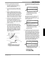
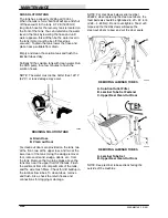
The vacuum fan drive belt is driven by the main
electric motor. Belt tension is maintained by a
tension spring. The belt is properly tensioned
when the spring is extended 1.25 in (32 mm)
beyond it’s collapsed length, approximately
6.88 in (175 mm). Thread the spring eye bolt in or
out of the fan mounting bracket to change the
spring length. Check belt condition and tension
after every 50 hours of operation.
WARNING: Strong Vacuum. Keep Away
From Fan Inlet When Fan Is Running.
WARNING: Moving Belt. Keep Away.
PUMP DRIVE BELT
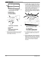
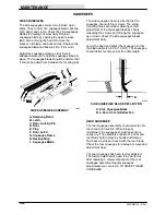
The pump drive belt is driven by the main electric
motor. Belt tension is maintained by an
adjustment bolt that pivots the pump assembly
away from the electric motor. The belt is properly
tensioned when it deflects 0.12 in (3 mm) from a
force of 1.5 to 2 lb (0.7 to 0.9 kg) applied at belt
midpoint. Check belt tension after every 50 hours
of operation.
WARNING: Moving Belt. Keep Away.
STATIC DRAG CHAIN
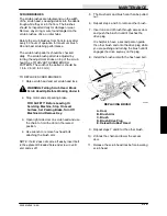
A static drag chain is provided to prevent the
build-up of static electricity in the machine. This
chain is attached below the machine frame, and
drags on the floor.
Check the chain periodically for wear. Make sure
that it is making contact with the floor at all times.
SCRUB BRUSH DRIVE CHAINS
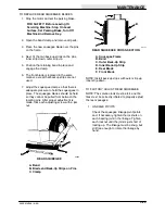
Each of the two scrub brush drive chains are
driven by an electric motor. The chains are
covered by a chain case and are partially
immersed in SAE 30 engine oil. Check the oil
level after every 50 hours of operation.
Chain tension is adjusted by moving the mounting
location of the electric motors. The motor
mounting holes are slotted. The chains are
properly tensioned when there is 0.12 in (3 mm)
slack midway between the sprockets. Check the
chain tension after every 100 hours of operation.
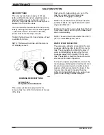
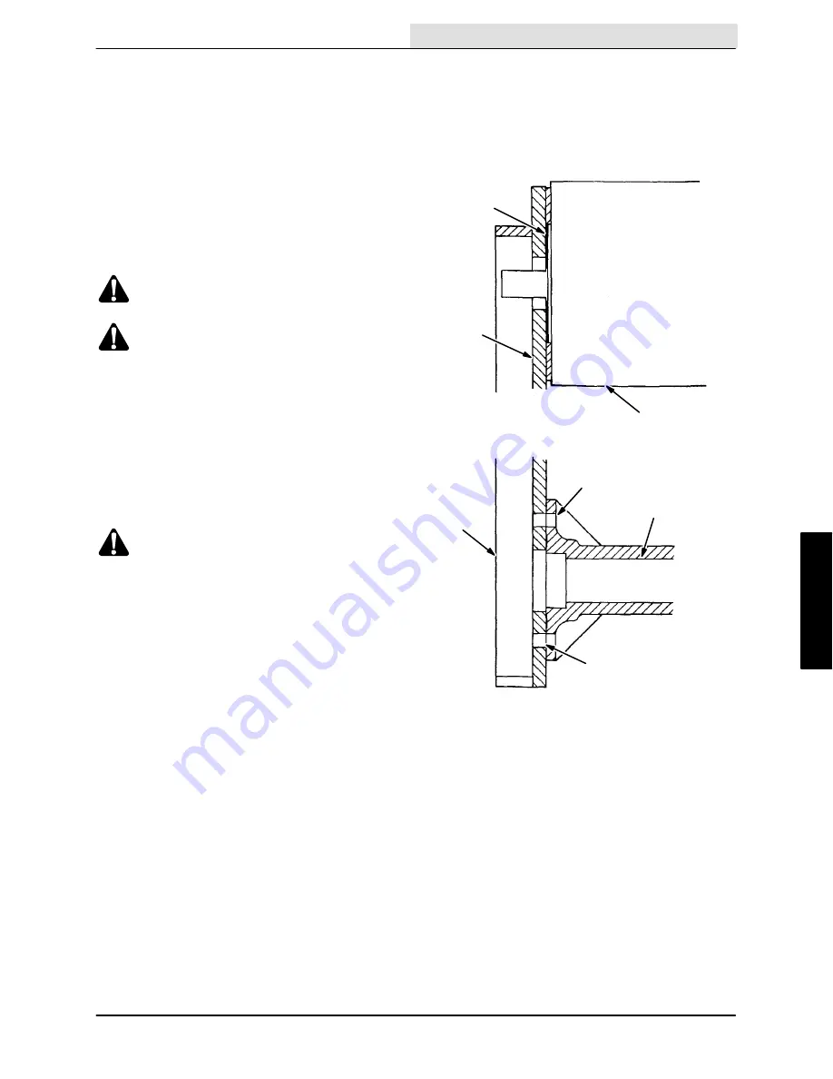
When replacing drive chains, be sure to use new
gaskets and RTV sealant where they were
originally used. Also, use Loctite on the four motor
mounting bolts.
A
B
C
D
E
F
G
01151
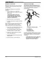
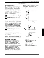
SCRUB BRUSH DRIVE CROSS-SECTION
A. Gasket
B. RTV Sealant in Slot after the
Bolt is in Place
C. Electric Motor
D. Loctited Mounting Bolts (4)
E. Bearing Housing
F. Brush Drive Arm
G. Sealant Around the Diameter
Summary of Contents for 550
Page 10: ...GENERAL INFORMATION 550E MM149 3 94 viii ...
Page 12: ...OPERATION 550E MM149 3 91 2 2 ...
Page 30: ...OPERATION 550E MM149 9 00 2 20 ...
Page 32: ...MAINTENANCE 550E MM149 3 91 3 2 ...
Page 62: ...MAINTENANCE 550E MM149 2 05 3 32 ...
Page 66: ...APPENDIX 550E MM149 3 91 4 4 ...
Page 74: ...STANDARD PARTS 550E MM149 5 01 6 4 Fig 2 Replacement Brushes 1 ...
Page 96: ...STANDARD PARTS 550E MM149 5 01 6 26 Fig 17 Electric Motor Group 1 2 3 4 5 6 ...
Page 105: ...STANDARD PARTS 6 35 550E MM149 5 01 Fig 23 Electrical Schematic 1 2 3 4 5 01228 550E ...
Page 106: ...STANDARD PARTS 550E MM149 5 01 6 36 Fig 23 Electrical Schematic 1 2 3 4 5 01228 550E ...
Page 117: ...STANDARD PARTS 6 47 550E MM149 5 01 Fig 31 Hydraulic Schematic 001330 005607 02361 550E ...
Page 118: ...STANDARD PARTS 550E MM149 5 01 6 48 Fig 32 Hydraulic Schematic 005608 11118 550E ...
Page 168: ...OPTIONS 550E MM149 9 99 8 18 ...
Page 182: ...BREAKDOWNS 550E MM149 10 10 9 14 ...

