MAINTENANCE
3-19
550E MM149 (6--96)
SCRUB BRUSHES
The scrub brushes are tubular and run the width
of the scrub head, sweeping debris into the debris
trough while they scrub the floor. The brushes
should be inspected daily for damage or wear.
Remove any string or wire found tangled on the
scrub brushes, drive, or idler hubs.
Rotate the scrub brushes from front-to-rear after
every 50 hours of operation for maximum brush
life and best scrubbing performance.
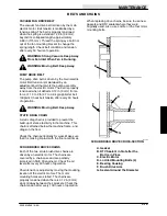
The scrub brush patterns should be checked
daily. The scrub brush pattern is adjusted by
turning the adjustment knobs on top of the scrub
head. See
TO ADJUST SCRUB BRUSH
PATTERN
. The width of the patterns should be
1.5 to 2 in (40 to 50 mm).
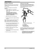
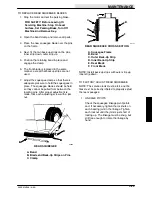
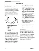
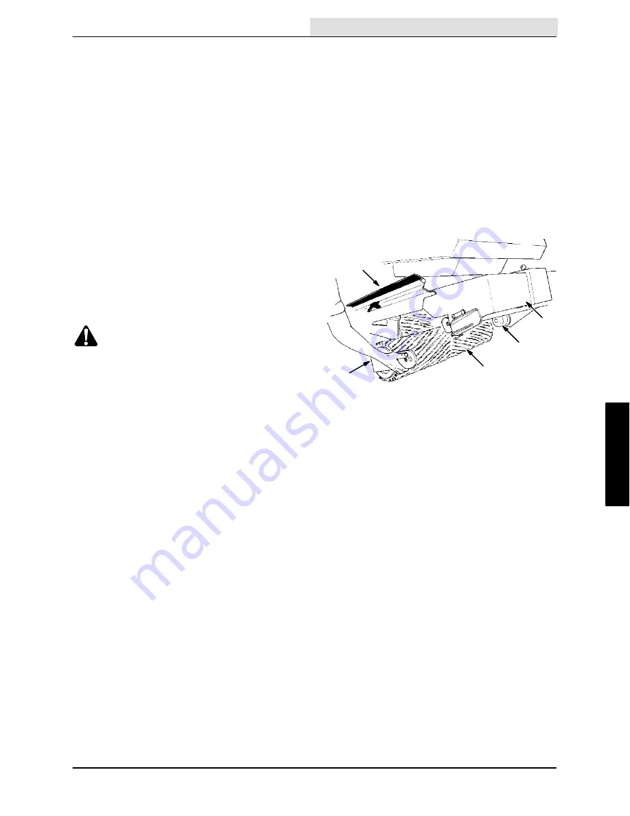
TO REPLACE SCRUB BRUSHES
1. Raise scrub head and set scrub head lock.
WARNING: Falling Scrub Head. Block
Scrub Head Up Before Working Under It.
2. Stop motor and set parking brake.
FOR SAFETY: Before Leaving Or
Servicing Machine; Stop On Level
Surface, Set Parking Brake, Turn Off
Machine And Remove Key.
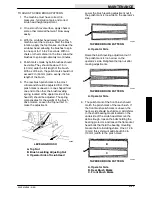
3. Open right side door on scrub head and use
the chain to hold the door in the raised
position.
4. Use wrench to remove hex head bolt
attaching the brush arm.
NOTE: If arm does not come off easily, insert bolt
in the adjacent threaded hole and screw in until
arm comes off.
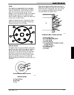
5. The brush arm and brush can then be pulled
out.
6. Repeat step 4 and 5 to remove other brush.
7. Insert one end of brush through access door
and push the brush in until it touches the
drive plug.
It is helpful to have a second person guide
the other brush end onto the drive plug while
you are pushing and turning the brush until it
engages the drive keyway on the plug.
8. Install the brush arm with the hex head bolt.
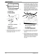
E
D
C
A
B
00287
REPLACING BRUSH
A. Door
B. Brush Arm
C. Brush
D. Brush Drive Plug
E. Raised Scrubber Head
9. Repeat steps 7 and 8 for the other brush.
10. Unhook the chain and lower the access
door.
11. Release the scrub head lock before lowering
scrub head.
Summary of Contents for 550
Page 10: ...GENERAL INFORMATION 550E MM149 3 94 viii ...
Page 12: ...OPERATION 550E MM149 3 91 2 2 ...
Page 30: ...OPERATION 550E MM149 9 00 2 20 ...
Page 32: ...MAINTENANCE 550E MM149 3 91 3 2 ...
Page 62: ...MAINTENANCE 550E MM149 2 05 3 32 ...
Page 66: ...APPENDIX 550E MM149 3 91 4 4 ...
Page 74: ...STANDARD PARTS 550E MM149 5 01 6 4 Fig 2 Replacement Brushes 1 ...
Page 96: ...STANDARD PARTS 550E MM149 5 01 6 26 Fig 17 Electric Motor Group 1 2 3 4 5 6 ...
Page 105: ...STANDARD PARTS 6 35 550E MM149 5 01 Fig 23 Electrical Schematic 1 2 3 4 5 01228 550E ...
Page 106: ...STANDARD PARTS 550E MM149 5 01 6 36 Fig 23 Electrical Schematic 1 2 3 4 5 01228 550E ...
Page 117: ...STANDARD PARTS 6 47 550E MM149 5 01 Fig 31 Hydraulic Schematic 001330 005607 02361 550E ...
Page 118: ...STANDARD PARTS 550E MM149 5 01 6 48 Fig 32 Hydraulic Schematic 005608 11118 550E ...
Page 168: ...OPTIONS 550E MM149 9 99 8 18 ...
Page 182: ...BREAKDOWNS 550E MM149 10 10 9 14 ...

