MAINTENANCE
550E MM149 (6--97)
3-28
C
B
A
D
E
F
G
H
I
00196
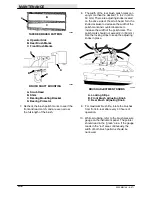
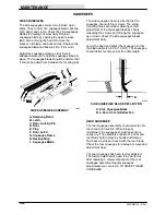
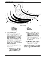
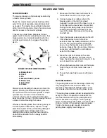
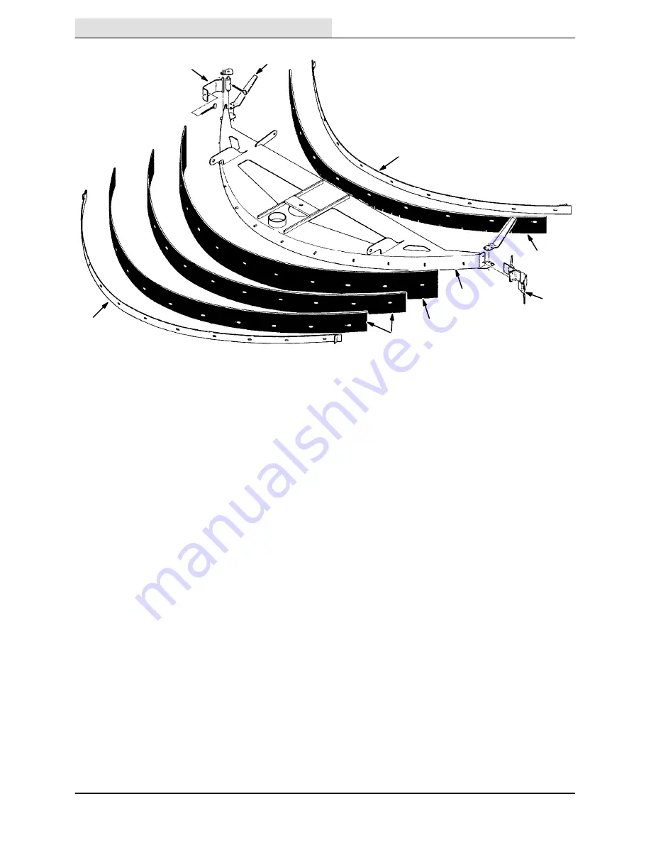
REAR SQUEEGEE
A. Adjuster
F. Frame
B. Spring Guide
G. Rear Blade
C. Front Band
H. Back-Up Strip
D. Front Blade
I.
Band
E. Band Clamp
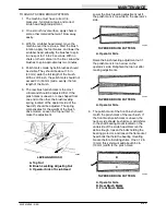
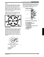
TO ADJUST REAR SQUEEGEE
1. Lower the rear squeegee and drive the
machine slowly forward to observe the
squeegee rollout. Adjust the squeegee roller
height adjustment stud or add or remove
washers from the casters to get an even
rollout. The top nut acts as a locknut. The
nut just under the squeegee frame is the
adjusting nut. Loosen the locking nut and
turn the adjusting nut clockwise to increase
down pressure, or counterclockwise to
decrease pressure. Tighten the locknut after
adjusting the adjusting nut.
2. Lower the rear squeegee and drive the
machine slowly forward to observe the tips
of the squeegee.
a. If both tips are too low, tighten both
eyebolts which increases the down
pressure on the back side of the
squeegee frame to lift both tips.
b. If both tips are too high, loosen both
eyebolts which decreases the down
pressure on the back side of the
squeegee frame to lower both tips.
c. If just one tip is too low, loosen the
eyebolt on the side that is too low. If the
tip is still too low, tighten the eyebolt on
the opposite side.
d. If just one tip is too high, tighten the
eyebolt on the side that is too high. If
the tip is still too high, loosen the
eyebolt on the opposite side.
NOTE: The number of washers on the squeegee
tip casters may need to be changed to properly
adjust the squeegee tips.
Summary of Contents for 550
Page 10: ...GENERAL INFORMATION 550E MM149 3 94 viii ...
Page 12: ...OPERATION 550E MM149 3 91 2 2 ...
Page 30: ...OPERATION 550E MM149 9 00 2 20 ...
Page 32: ...MAINTENANCE 550E MM149 3 91 3 2 ...
Page 62: ...MAINTENANCE 550E MM149 2 05 3 32 ...
Page 66: ...APPENDIX 550E MM149 3 91 4 4 ...
Page 74: ...STANDARD PARTS 550E MM149 5 01 6 4 Fig 2 Replacement Brushes 1 ...
Page 96: ...STANDARD PARTS 550E MM149 5 01 6 26 Fig 17 Electric Motor Group 1 2 3 4 5 6 ...
Page 105: ...STANDARD PARTS 6 35 550E MM149 5 01 Fig 23 Electrical Schematic 1 2 3 4 5 01228 550E ...
Page 106: ...STANDARD PARTS 550E MM149 5 01 6 36 Fig 23 Electrical Schematic 1 2 3 4 5 01228 550E ...
Page 117: ...STANDARD PARTS 6 47 550E MM149 5 01 Fig 31 Hydraulic Schematic 001330 005607 02361 550E ...
Page 118: ...STANDARD PARTS 550E MM149 5 01 6 48 Fig 32 Hydraulic Schematic 005608 11118 550E ...
Page 168: ...OPTIONS 550E MM149 9 99 8 18 ...
Page 182: ...BREAKDOWNS 550E MM149 10 10 9 14 ...

