

OPERATION
16
Tennant 5540/5560 (08--05)
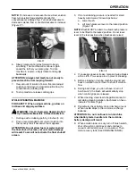
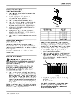
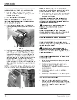
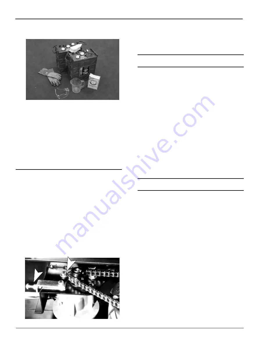
a. Mix a strong solution of baking soda and water
(Figure 31).
FIG. 31
b. Brush the solution sparingly over the battery
tops and cable connectors.
NOTE:
Do not allow baking soda solution to enter
battery cells.
c. Use a wire brush to clean the battery terminals
and cable connectors.
d. After cleaning, apply a coating of clear battery
post protectant to the terminals and cable
connectors.
5. Check for loose or worn cables. Replace if worn.
DRIVE CHAIN MAINTENANCE
FOR SAFETY: Before leaving or servicing
machine, stop on level surface and turn off
machine.
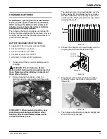
Inspect drive chain for proper tension. Chain should
flex between 6.35mm (0.25 in.) and 12.7mm (0.50 in.)
from center. If chain flexes more than 12.7mm
(0.50 in.), chain should be tightened. To tighten chain,
follow steps below:
1. Turn main switch to the off position and pull out
the main circuit breaker button.
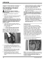
2. From operators right side of machine, locate and
loosen 4 motor mount bolts, do not remove bolts.
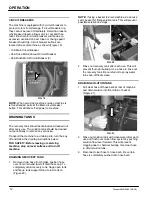
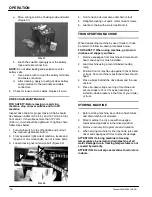
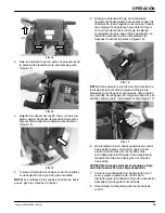
3. Loosen locking nut on tension bolt (Figure 32).
FIG. 32
4. Turn tension bolt clockwise until chain is taut.
5. Retighten locking nut and 4 motor mount screws.
6. Lubricate chain with a water resistant oil.
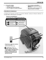
TRANSPORTING MACHINE
When transporting machine by use of trailer or truck,
be certain to follow tie--down procedures below:
FOR SAFETY: When using machine, go slow on
inclines and slippery surfaces.
1. Remove squeegee from machine and raise brush
head. Leave pad or brush installed.
2. Load machine using a recommended loading
ramp.
3. Position front of machine up against front of trailer
or truck. Once machine is positioned, lower brush
head.
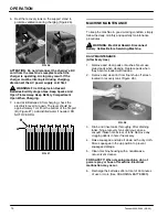
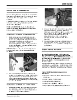
4. Place a block behind the drive wheel and the rear
casters.
5. Place tie--down straps over top of machine and
secure straps to floor. It may be necessary to
install tie--down brackets to the floor of your trailer
or truck.
STORING MACHINE
1. Before storing machine, be certain to flush tanks
and drain machine of all water.
2. Store machine in a dry area with squeegee
removed and pad driver in the raised position.
3. Remove recovery lid to promote air circulation.
4. When storing machine for short periods, raise pad
driver and squeegee off floor to prevent damage.
ATTENTION: If storing machine in freezing
temperatures, be certain to drain machine of all
water. Damage due to freezing temperatures is not
covered by warranty.
ATTENTION: Do not expose machine to rain; store
indoors.


