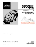
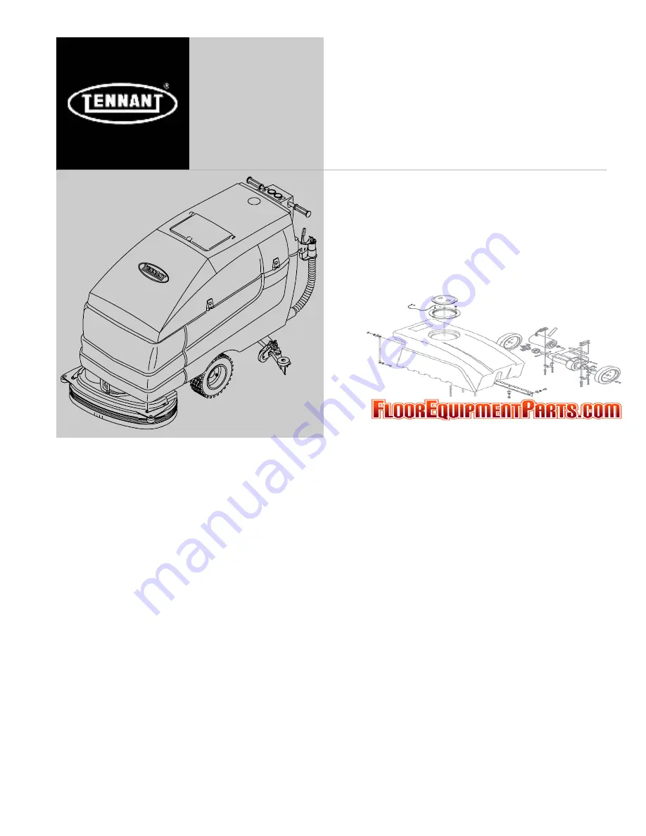
background image

5700EE

*331535*

www.tennantco.com

Walk--Behind Scrubber

Operator Manual

331535

Rev. 00 (09-2006)

North America / International

ES Extended Scrub System

R

(Electric)

(10000000--

)

Summary of Contents for 5700EE

Page 1: ...5700EE 331535 www tennantco com Walk Behind Scrubber Operator Manual 331535 Rev 00 09 2006 North America International ES Extended Scrub System R Electric 10000000 ...

Page 2: ...TECT THE ENVIRONMENT Please dispose of packaging materials old machine components such as batteries hazardous fluids such as antifreeze and oil in an environmentally safe way according to local waste disposal regulations Always remember to recycle MACHINE DATA Please fill out at time of installation for future reference Model No Serial No Machine Options Sales Rep Sales Rep phone no Customer Numbe...

Page 3: ...UUM WAND 36 POWER WAND 40 MAINTENANCE 45 MAINTENANCE CHART 45 LUBRICATION 46 REAR CASTERS 46 TRANSAXLE 46 BATTERIES 46 CHARGING THE BATTERIES 47 Page ELECTRIC MOTORS 49 SCRUB HEAD 50 DISK BRUSH SCRUB HEAD SKIRT 50 ADJUSTING THE SCRUB HEAD SKIRT 50 REPLACING THE SCRUB HEAD SKIRT 51 CYLINDRICAL BRUSH SCRUB HEAD SKIRTS 52 ADJUSTING THE SCRUB HEAD SKIRTS 52 REPLACING THE SCRUB HEAD SKIRTS 52 REMOVING ...

Page 4: ...CONTENTS 5700EE 331535 9 06 2 Page SPECIFICATIONS 74 GENERAL MACHINE DIMENSIONS CAPACITIES 74 GENERAL MACHINE PERFORMANCE 75 POWER TYPE 75 TIRES 75 MACHINE DIMENSIONS 76 INDEX 77 ...

Page 5: ...d and authorized Unless operation manual is read and understood In flammable or explosive areas unless designed for use in those areas 2 Before starting machine Make sure all safety devices are in place and operate properly Check brakes and steering for proper operation if so equipped 3 When using machine Go slow on inclines and slippery surfaces Use care when backing machine Follow mixing and han...

Page 6: ...label becomes damaged or illegible install a new label in its place BATTERY CHARGING LABEL LOCATED ON THE UNDERSIDE OF THE SOLUTION TANK FLAMMABLE SPILLS LABEL LOCATED ON THE OPERATOR CONSOLE FOR SAFETY LABEL LOCATED ON THE OPERATOR CONSOLE FLAMMABLE MATERIALS LABEL LOCATED ON THE UNDERSIDE OF THE SOLUTION TANK COVER 10066 ...

Page 7: ...R SAFETY Do not operate machine unless operation manual is read and understood Check the machine for shipping damage Check to make sure the machine is complete per shipping instructions Keep your machine regularly maintained by following the maintenance information in this manual We recommend taking advantage of a regularly scheduled service contract from your Tennant representative Order parts an...

Page 8: ...nk B Solution tank fill opening C Recovery tank D Console panel E Squeegee F Squeegee lever G Squeegee down pressure cams H Squeegee leveling knob I Parking brake option J Recovery tank drain hose K Solution tank hose L Support arm M Stop arm N Batteries O Scrub head P Scrub brush access cover Q Scrub brush idler door ...

Page 9: ... the machine Solution flow Key switch Power wand Variable flow or rate ES Extended Scrub Circuit breaker 1 Recovery tank full Circuit breaker 2 Scrub brushes down and on Circuit breaker 3 Scrub brushes up and off Circuit breaker 4 Battery charge Circuit breaker 5 Scrub brush pressure Circuit breaker 6 ...

Page 10: ...tch option D Recovery tank full light E ES switch option F Battery discharge indicator G Brush pressure gauge H Scrub brushes down light I Scrub brushes switch J Hourmeter K On off key switch L Machine on light M Circuit breakers N Squeegee lever O Power kill switch option P Steering height adjustment latch Q Solution tank hose R Recovery tank drain hose S Speed reduction knob option ...

Page 11: ...speed and direction Forward Rotate the handles forward The further forward you rotate the handles the faster the machine will go Backward Rotate the handles toward you Turning Push the machine in the direction of the turn with the steering handles The machine will turn on the swivel casters ...

Page 12: ...ow lever controls the amount of solution flow to the floor Increase Push the lever forward Decrease Pull the lever backward NOTE A solenoid valve dispenses the solution to the scrub head The valve opens when the steering handles are rotated forward and closes when the steering handles are released in neutral position POWER WAND SWITCH OPTION The power wand switch turns on and off the power wand so...

Page 13: ... the switch The switch will light up Off Press the bottom of the switch BATTERY DISCHARGE INDICATOR The battery discharge indicator shows the charge level of the batteries The meter s needle should be at the top of the green zone when the batteries are fully charged As the batteries discharge the needle will move into the bottom red zone Recharge the batteries when the needle remains in the bottom...

Page 14: ...rush circuit breakers to trip Adjust the brush pressure during scrubbing with the scrub brushes switch SCRUB BRUSHES DOWN LIGHT The scrub brushes down light comes on when the scrub brushes are lowered enough to touch the floor The light goes off when the scrub brushes are raised off the floor On machines serial number 017946 and above the light is located in the scrub brush switch On machines belo...

Page 15: ...e Press the top of the switch Watch the brush pressure gauge Decrease brush pressure Press the bottom of the switch Watch the brush pressure gauge NOTE The scrub brushes do not start until the steering handles are rotated forward or backward HOURMETER The hourmeter records the number of hours the machine has been powered on This information is useful when servicing the machine MACHINE ON LIGHT The...

Page 16: ...ever Raise squeegee and stop vacuum Pull the lever up and move it to the right to lock the lever in the up position NOTE Raise the squeegee before reversing the machine SOLUTION TANK LOCKING TAB The solution tank locking tab allows the solution tank to be locked down The locking tab is located on the corner of the operator console SPEED REDUCTION KNOB OPTION The speed reduction knob adjusts the ma...

Page 17: ...et manually by pressing the reset button after the breaker has cooled down If the overload that caused the circuit breaker to trip is still there the circuit breaker will continue to stop current flow until the problem is corrected The circuit breakers are located on each side of the operator console The chart shows the circuit breakers and the electrical components they protect Circuit Breaker Ra...

Page 18: ...ed to drain the recovery tank The drain hose plug is removed by turning the plug latch to loosen the plug and pulling the plug out of the drain hose The drain hose is plugged by placing the hose plug in the end of the hose and turning the plug latch to tighten the plug SUPPORT ARM The support arm holds up the solution tank when the tank is lifted The support arm engages when the solution tank is l...

Page 19: ...gee leveling knob adjusts the deflection at the ends of the squeegee Increase Turn the squeegee leveling knob counter clockwise to increase the deflection at the end of the squeegees Decrease Turn the squeegee leveling knob clockwise to decrease the deflection at the end of the squeegees PARKING BRAKE OPTION The parking brake is controlled with a foot pedal and a release lever located by the squee...

Page 20: ...he floor As the machine is moved forward the squeegee wipes the dirty solution off the floor which is then picked up and drawn into the recovery tank The steering handles control the direction and speed of the machine in forward or reverse By rotating the steering handles forward the machine propels forward By rotating the handles towards you the machine propels backward When using the ES mode the...

Page 21: ...rubbing brushes Remove any string banding plastic wrap or other debris wrapped around them Check the squeegees for damage wear and for deflection adjustment Check the vacuum hose for debris or blockage ES machines check the detergent tank level Drain and clean the recovery tank ES machines drain and clean the solution tank and ES filter Rinse level sensors Empty and clean the debris tray if applic...

Page 22: ...00EE 331535 9 06 20 STARTING THE MACHINE 1 Turn the machine power on 2 Release the machine parking brake if your machine has this option FILLING THE TANKS 1 Start the machine 2 Drive the machine to the filling site ...

Page 23: ...ake if so equipped turn off machine and remove key 4 Set the parking brake if your machine has this option NOTE If you are going to scrub in the ES mode the recovery tank can be partially filled to extend scrub time Make sure the ES system is on If you do not want to use the ES system make sure the ES system is off DO NOT fill the recovery tank ...

Page 24: ...t into the solution tank fill opening Continue filling the solution tank with water 25 mm 1 in below the bottom of the solution fill opening channel FOR SAFETY Follow mixing and handling instructions on chemical containers NOTE Floor conditions water condition amount of soilage types of soilage and brush action all play an important role in determining the type and concentration of detergent used ...

Page 25: ...ing high gloss coated floors Nylon scrub brush Recommended for scrubbing coated floors Cleans without scuffing Super abrasive bristle scrub brush Nylon fiber impregnated with abrasive grit to remove stains and soilage Strong action on any surface performing well on buildup grease or tire marks Heavy duty stripping pad This black pad is for stripping floors Cuts through old heavy finishes easier to...

Page 26: ...coated floors Cleans without scuffing Cylindrical super abrasive bristle scrub brush Nylon fiber impregnated with abrasive grit to remove stains and soilage Strong action on any surface performing well on buildup grease or tire marks NOTE Cylindrical scrub brushes must be installed with the herringbone patterns on the brushes pointing towards each other for best debris pick up 1 Start the machine ...

Page 27: ...s on 5 Adjust the solution flow to the floor as needed 6 Drive the machine forward and scrub as required WARNING Flammable materials or reactive metals can cause an explosion or fire Do not pickup 7 Adjust brush pressure for cleaning application with the scrub brushes switch while watching the brush pressure gauge ...

Page 28: ...ea to be cleaned with the machine First make a pass over the area scrubbing with the squeegee up This dispenses solution over the area allowing the solution to soak on the floor Let the solution remain on the floor for 15 to 20 minutes Then make a second pass scrubbing with the squeegee down FOR SAFETY When using machine go slow on inclines and slippery surfaces ...

Page 29: ...7 5700EE 3315353 9 06 STOP SCRUBBING 1 Release the steering handles 2 Raise the scrub brushes with the scrub brushes switch until the scrub brushes down light goes off 3 Raise the squeegee with the squeegee lever ...

Page 30: ...hen can be filled again for additional scrubbing If you used the machine in ES mode the solution tank should also be drained and cleaned when you are finished scrubbing 1 Stop scrubbing 2 Drive the machine next to a floor drain or sink 3 Turn the machine power off FOR SAFETY Before leaving or servicing machine stop on level surface and turn off machine 4 Set the parking brake if your machine has t...

Page 31: ...mode Lift the solution tank cover and flush out the solution tank with clean water through the fill opening and the top access hole Rinse the filter s at the bottom of the solution tank NOTE Do not use steam to clean the tank 8 ES mode When the solution tank has completely drained replace the drain hose plug in the solution tank drain hose and place the solution tank drain hose back onto the mount...

Page 32: ...unting clip 10 Remove the drain hose plug while holding the hose up then slowly lower the drain hose to the floor drain or sink 11 Lift the solution tank to reach the recovery tank 12 Flush out the inside of the recovery tank with clean water NOTE Do not use steam to clean the tank ...

Page 33: ... on the side of the recovery tank 15 Remove and clean the vacuum fan filter located in the recovery tank Clean by shaking dust or rinsing pleats with low pressure water Insert the filter back in to the recovery tank when finished NOTE Be sure the vacuum filter is dry before reinstalling it in the machine ...

Page 34: ...ry tank drain hose Place the recovery tank drain hose back onto the mounting clip on the machine 17 Pull up on the support arm and lower the solution tank Push the stop arm in to completely lower the solution tank 18 Cylindrical scrub head Remove and clean the debris trough Place the trough back in the scrub head ...

Page 35: ...FOR SAFETY Before leaving or servicing machine stop on level surface set parking brake if so equipped turn off machine and remove key OPERATION ON INCLINES Drive the machine slowly on inclines FOR SAFETY When using machine go slow on inclines and slippery surfaces The maximum rated climb and descent incline with empty tanks is 8_ with full tanks is 6_ ...

Page 36: ... with the machine powered off Check the tank cover seals for damage and wear Clean the vacuum fan inlet filter Check the condition of the scrubbing brushes Remove any string banding plastic wrap or other debris wrapped around them Check the squeegees for damage wear and for deflection adjustment Check the vacuum hose for debris or blockage ES machines check the detergent tank level Drain and clean...

Page 37: ...bright sunlight Install sensor sun shield s Little or no solution flow to the floor Solution tank empty Fill solution tank Solution control cable broken or out of adjustment Replace and or adjust cable Solution flow turned off Turn solution flow on Solution supply lines plugged Flush solution supply lines Solution supply line filter dirty Clean filter Solution solenoid clogged or stuck Clean or re...

Page 38: ...s pick up of spills that are out of reach of the machine WARNING Flammable materials or reactive metals can cause an explosion or fire Do not pickup 1 Turn the machine power off FOR SAFETY Before leaving or servicing machine stop on level surface and turn off machine 2 Set the parking brake if your machine has this option ...

Page 39: ...353 9 06 3 Remove the squeegee suction hose from the top of the squeegee 4 Put together the wand and the wand hose 5 Connect the vacuum wand hose and the squeegee suction hose with the adapter 6 Turn the machine power on 10080 ...

Page 40: ...N 5700EE 331535 9 06 38 7 Lower the squeegee with the squeegee lever to turn the vacuum system on 8 Vacuum the floor 9 When finished raise the squeegee to shut off the vacuum 10 Turn the machine power off 06599 ...

Page 41: ...OPERATION 39 5700EE 3315353 9 06 11 Remove the vacuum hose from the squeegee suction hose 12 Reconnect the squeegee suction hose to the top of the squeegee ...

Page 42: ...out of reach of the machine WARNING Flammable materials or reactive metals can cause an explosion or fire Do not pickup 1 Turn the machine power off FOR SAFETY Before leaving or servicing machine stop on level surface and turn off machine 2 Set the parking brake if your machine has this option 3 Remove the squeegee suction hose from the top of the squeegee ...

Page 43: ...se with the adapter 5 Open the solution tank cover Attach the end of solution hose to the quick disconnect Push the connector in until it stops Pull on the hose to make sure it is connected 6 Attach the other ends of the solution and vacuum hoses to the power wand 7 Turn the machine power on ...

Page 44: ...urn the vacuum system on 9 Switch the power wand on 10 Squeeze the solution lever on the power wand to spray solution on the floor Scrub the floor with the brush side of the cleaning tool 11 Vacuum up the solution by turning over the cleaning tool so the squeegee side is down 06202 ...

Page 45: ... wheels on the tool by turning the black adjustment knob NOTE The wheels are properly adjusted when the squeegee blades deflect slightly while the tool is pushed back and forth 12 When finished switch the power wand off 13 When finished raise the squeegee to shut off the vacuum 14 Disconnect the solution hose from the machine 06604 ...

Page 46: ...6 44 15 Remove the vacuum hose from the squeegee suction hose 16 Disconnect the other ends of the solution and vacuum hoses from the power wand 17 Turn the machine power off 18 Reconnect the squeegee suction hose to the squeegee ...

Page 47: ...1 Machine Check for leaks 1 6 Disk scrub head skirt Check adjustment 1 Check for damage and wear 1 6 Cylindrical scrub head Check adjustment 4 y skirts Check for damage and wear 4 50 Hours 5 Front tires Check air pressure 2 8 Cylindrical brushes Check taper and rotate front to rear 2 100 Hours 4 Rear casters Lubricate SPL 2 9 Cylindrical scrub brush drive belts Check tension 2 500 Hours 10 Vacuum ...

Page 48: ...e of the batteries is limited by the number of charges the batteries receive To get the most life from the batteries charge them when the battery discharge indicator s needle remains in the red zone of the indicator Periodically clean the top surface of the batteries and the terminals and check for loose connections Use a strong solution of baking soda and water Brush the solution sparingly over t...

Page 49: ...r than the other battery cells 0 050 or more the cell is damaged shorted or is about to fail NOTE Do not take readings immediately after adding distilled water If the water and acid are not thoroughly mixed the readings may not be accurate Check the hydrometer readings against the following chart to determine the remaining battery charge level SPECIFIC GRAVITY BATTERY at 27_ C 80_F CHARGE 1 265 10...

Page 50: ...nough distilled water to cover the battery plates DO NOT OVERFILL The batteries can overflow during charging due to expansion NOTE Make sure the battery caps are in place while charging FOR SAFETY When maintaining or servicing machine avoid contact with battery acid 6 Plug the charger connector into the battery connector WARNING Batteries emit hydrogen gas Explosion or fire can result Keep sparks ...

Page 51: ...tor on the machine FOR SAFETY When maintaining or servicing machine avoid contact with battery acid 11 Check the electrolyte level in each battery cell after charging If needed add distilled water to raise the electrolyte level to about 12 mm 0 4 in below the bottom of the sight tubes 12 Lower the solution tank 13 Pull up on the support arm and rotate the stop arm out of the way to allow the solut...

Page 52: ...crub head on a level floor 2 Turn the machine power off FOR SAFETY Before leaving or servicing machine stop on level surface and turn off machine 3 Check to see if the scrub head skirt touches the floor all the way around the scrub head 4 If the skirt needs to be adjusted pull the strap end away from the skirt Loosen the strap from the buckle and move the skirt up or down to touch the floor NOTE R...

Page 53: ...urn off machine 3 Pull the strap end away from the skirt Loosen and pull the strap from the buckle 4 Pull the old skirt off the scrub head 5 Put the new skirt on the scrub head lining up the notches under the rollers 6 Pull the strap tight through the buckle and attach the strap end to the skirt using the hook and loop fastener 7 Adjust the skirt as stated in ADJUSTING THE SCRUB HEAD SKIRT ...

Page 54: ...urn off machine 3 Check to see if the scrub head skirts touch the floor 4 If any of the skirts needs adjusting loosen the retainer strip hardware and slide the skirt to the proper adjustment Tighten the retainer strip hardware REPLACING THE SCRUB HEAD SKIRTS 1 Raise the scrub head 2 Turn the machine power off FOR SAFETY Before leaving or servicing machine stop on level surface and turn off machine...

Page 55: ... two brush types disk and cylindrical 1 Lower the scrub head 2 Turn the machine power off FOR SAFETY Before leaving or servicing machine stop on level surface and turn off machine 3 Remove the machine front cover 4 Disconnect the solution line from the scrub head tee fitting 5 Disconnect the wire harness ...

Page 56: ...t the actuator from the scrub head by removing the clevis pin 9 To install the scrub head connect the lift arms to the scrub head with the two clevis pins 10 Connect the scrub head to the guide with the clevis pin 11 Make sure the actuator tube lines up with the mark made earlier on the actuator shaft If not turn the actuator tube until it does Connect the actuator to the scrub head with the clevi...

Page 57: ...he scrub head to the floor at all four corners The scrub head should measure the same on all four corners 3 If the scrub head is not level at all four corners loosen the jam nut on the adjustment screw located on the top of the scrub head Turn the adjustment screw until the scrub head measures level Tighten the jam nut 4 Install the machine front cover 5 Cylindrical scrub head Check the brush patt...

Page 58: ...ise one brush will be more aggressive than the other Cleaning pads must be placed on pad drives before they are ready to use The cleaning pad is held in place by a pad holder Cleaning pads need to be cleaned immediately after using with soap and water Do not wash the pads with a pressure washer Hang dry pads or lie flat to dry REPLACING THE DISK BRUSHES 1 Raise the scrub head 2 Turn the machine po...

Page 59: ...drive hub 6 Pull the brush out from under the scrub head 7 Place the new scrub brush on the floor in front of the scrub head Push the brush under the scrub head 8 Line up the brush drive socket with the drive plug 9 Lift the scrub brush into the drive plug 10 Check to make sure the brush is securely mounted on the brush drive hub 11 Close the scrub head access cover 12 Repeat for the other brush ...

Page 60: ...ive than the other REPLACING THE CYLINDRICAL BRUSHES 1 Raise the scrub head 2 Turn the machine power off and set the parking brake if your machine has this option FOR SAFETY Before leaving or servicing machine stop on level surface and turn off machine 3 Push down on the mounting spring and the idler door then pull out on the bottom of the door Push down on the spring until the door releases from ...

Page 61: ...RUSH PATTERN NOTE Check the tires for correct tire pressure and make sure the solution tank is full before checking or adjusting the brush pattern 1 Apply chalk or some other material that will not blow easily away to a smooth level floor 2 Raise the scrub head Position the scrub head over the chalked area 3 Set the parking brake if your machine has this option 4 Lower the scrub head for 15 to 20 ...

Page 62: ...hes will have to be adjusted to straighten the brush pattern A Remove the idler door by pushing down on the mounting spring and the idler door then pulling out on the bottom of the door Push down on the spring until the door releases from the scrub head Pull the idle plug off the brush B While holding the flat end of the idler shaft with a wrench loosen the mounting screw on the outside of the idl...

Page 63: ...e scrub head Turn the adjustment screw clockwise to increase the front brush pattern width Turn the adjustment screw counter clockwise to increase the back brush pattern width Check the brush patterns again Adjust until the front and back patterns are the same width Tighten the jam nut SOLUTION SYSTEM RECOVERY TANK The recovery tank stores recovered solution The recovery tank should be drained and...

Page 64: ...n tank stores the cleaning solution The solution tank does not require regular maintenance If deposits form on the bottom of the tank rinse the tank with a strong blast of warm water The tank can be flushed through the fill opening and top access hole ES option The solution tank should be drained and cleaned daily The solution tank contains one standard solution line filter and one solution line f...

Page 65: ... for leveling and deflection The deflection and leveling of the squeegee blades should be checked daily or when scrubbing a different type of floor The squeegee assembly can be removed from the squeegee pivot to prevent damage during transport of the machine or when changing to a different squeegee width REMOVING THE SQUEEGEE ASSEMBLY 1 Raise the squeegee 2 Turn the machine power off and set the p...

Page 66: ...t 4 Tighten the mounting knobs 5 Push the squeegee suction hose on the squeegee LEVELING THE SQUEEGEE Leveling of the squeegee assures even contact the length of the squeegee blade with the surface being scrubbed Make sure this adjustment is done on an even level floor 1 Turn the machine power on 2 Lower the squeegee 3 Drive the machine forward then turn the machine power off 4 Look at the deflect...

Page 67: ...ine moves forward with the squeegee lowered to the floor The best deflection is when the squeegee wipes the floor just dry with a minimum amount of deflection 1 Turn the machine power on 2 Lower the squeegee 3 Drive the machine forward and look at the deflection of the squeegee blade The correct amount of deflection is 12 mm 0 50 in for scrubbing smooth floors and 15 mm 0 62 in for rough floors 4 ...

Page 68: ...des the front and back Each blade has four wiping edges To use them all start with one wiping edge To use the next wiping edge rotate the blade end for end To use the next wiping edge rotate the top edges down bottom edges up To use the last edge rotate the blade end for end Replace any worn or damaged squeegee blades REPLACING OR ROTATING THE REAR SQUEEGEE BLADE 1 Make sure the squeegee is raised...

Page 69: ... touch Do not overtighten REPLACING OR ROTATING THE FRONT SQUEEGEE BLADE 1 Make sure the squeegee is raised off the floor 2 Turn the machine power off and set the parking brake if your machine has this option FOR SAFETY Before leaving or servicing machine stop on level surface and turn off machine 3 Remove the squeegee from the machine See REMOVING THE SQUEEGEE ASSEMBLY 4 Remove the rear squeegee ...

Page 70: ...on the retainer plate 8 Push the retainer plate forward Tighten the two outside knobs on top of the squeegee assembly 9 Insert the rear squeegee blade and retainer Tighten the two rear blade retention knobs until the ends of the front and rear squeegee blades touch Do not overtighten 10 Install the squeegee assembly on the squeegee pivot See INSTALLING THE SQUEEGEE ASSEMBLY 11 Adjust the squeegee ...

Page 71: ...ing an old belt measure and record the belt tension before removal so that the belt can be reinstalled at the same tension If the old belt tension was not recorded the recommended force per old belts is 1 03 to 1 14 kg 2 28 to 2 52 lb with a deflection of 3 mm 0 1 in Check the belt tension and wear every 100 hours of operation STATIC DRAG CHAIN A static drag chain prevents the buildup of static el...

Page 72: ...MACHINE If the machine becomes disabled it can be pushed if necessary Unplug the drive motor from the electrical harness before attempting to push a disabled machine The machine will become easier to maneuver when it is unplugged ATTENTION Do not push the machine for a long distance and without unplugging the drive motor or damage may occur to the propelling system Only push a disabled machine for...

Page 73: ...onto the truck or trailer 3 To winch the machine onto the truck or trailer attach the winching chains to the rear tie down locations on either side of the machine frame by the rear casters 4 Unplug the drive motor from the electrical harness before attempting to winch the machine The machine will become easier to maneuver when it is unplugged FOR SAFETY When loading machine onto truck or trailer u...

Page 74: ...e machine to prevent the machine from tipping The rear tie down locations are on either side of the machine frame by the rear casters 7 If the loading surface is not horizontal or is higher than 380 mm 15 in from the ground use a winch to unload machine If the loading surface is horizontal AND is 380 mm 15 in or less from the ground the machine may be pushed off the truck or trailer FOR SAFETY Whe...

Page 75: ...ne jack machine up at designated locations only Block machine up with jack stands STORAGE INFORMATION The following steps should be taken when storing the machine for extended periods of time 1 Drain and clean the solution and recovery tanks 2 Park the machine in a cool dry area 3 Remove the batteries or charge them after every three months FREEZE PROTECTION 1 Be sure the solution tank is empty 2 ...

Page 76: ...n scrub head 405 mm 16 in Cylindrical brush diameter 150 mm 6 in Cylindrical brush length for 800 mm 32 in scrub head 800 mm 32 00 in Squeegee width for 800 mm 32 in scrub head 1070 mm 42 in Scrubbing path width for 800 mm 32 in scrub head 800 mm 32 in Solution tank capacity recommended usage 114 L 30 gal Solution tank capacity maximum 133 L 35 gal Recovery tank capacity to full sensor 114 L 30 ga...

Page 77: ...eries 6 6 235 20 hr rate 30 kg 67 lb Type Use VDC Kw hp Electric Motors Scrub brush disk 36 0 45 0 60 Scrub brush cylindrical 36 0 56 0 75 Vacuum fan 36 0 56 0 75 Propelling 36 0 37 0 50 Type VDC amp Hz Phase VAC Chargers Smart 36 20 60 1 115 36 30 60 1 115 Chargers I t ti l 36 20 50 1 230 International 36 20 50 1 245 36 30 50 1 230 36 30 50 1 245 TIRES Location Type Size Pressure Front 2 Pneumati...

Page 78: ...SPECIFICATIONS 5700EE 331535 9 06 76 1600 mm 63 in 1660 mm 65 25 in 1065 mm 42 in 720 mm 28 25 in 1090 mm 43 in 10189 MACHINE DIMENSIONS ...

Page 79: ...uit breakers 15 ES switch 11 Height adjustment latch 10 Hourmeter 13 Machine on light 13 On off key switch 14 Power kill switch 15 Power wand switch 10 Recovery tank full light 11 Scrub brushes down light 12 Scrub brushes switch 13 Solution flow lever 10 Solution tank locking tab 14 Squeegee down pressure cams 17 Squeegee leveling knob 17 Squeegee lever 14 Steering handles 9 Symbols 7 Cylindrical ...

Page 80: ...t 10 Leveling the scrub head 55 Leveling the squeegee 64 Levers Parking brake 17 Solution flow 10 Squeegee 14 Lights Machine on 13 Recovery tank full 11 Scrub brushes down 12 Locks Solution tank 14 Lubrication 46 Rear casters 46 Transaxle 46 Lug nuts Front wheel 70 M Machine Jacking 73 Machine components 6 Machine dimensions 76 Machine tie down location 72 Maintenance 45 69 Intervals 45 Recommende...

Page 81: ...s 3 Stop arm 16 Support arm 16 Scrub brushes 56 61 Cylindrical 58 Adjusting pattern 59 61 Replacing 58 Disk 56 Replacing 56 Scrub brushes down light 12 Scrub brushes switch 13 Scrub head 50 56 Brush drive belt 69 Cylindrical brushes 52 Adjusting skirts 52 Replacing skirts 52 Disk brushes 50 Replacing skirt 51 Skirt adjusting 50 Leveling 55 Removing or replacing 53 55 Scrubbing Double 26 Normal 23 ...

Page 82: ...wn pressure cams 17 Squeegee leveling knob 17 Squeegee lever 14 Staring the machine 20 Static drag chain 69 Steering 34 Steering handles 9 Height adjustment 10 Stop arm 16 Stop scrubbing 27 Stop the machine 33 Storage information 73 Freeze protection 73 Support arm 16 Switches ES 11 On off key 14 Power kill 15 Power wand 10 Scrub brushes 13 T Tanks Recovery 61 Solution 62 Tie down location 72 Tire...

Reviews: