HYDRAULICS
5--4
6100 G/LP 330235 (9--00)
HYDRAULIC FLUID RESERVOIR
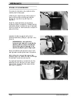
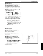
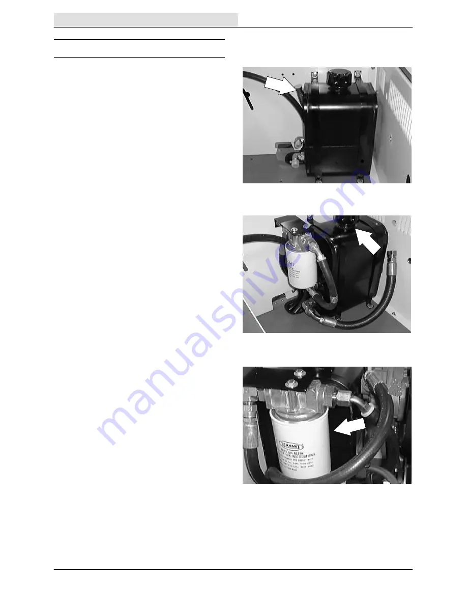
The reservoir is located on the right side of the
machine next to the engine.
A filler cap is mounted on top of the reservoir. It
has a built in breather and fluid level dipstick.
Replace the cap after every 800 hours of
operation.
Check the hydraulic fluid level at
operating
temperature
daily. The dipstick is marked with full
and add markings to indicate the level of hydraulic
fluid in the reservoir. Cold fluid level is mid-point of
add and full lines.
Lubricate the filler cap gasket with a film of
hydraulic fluid before putting the cap back on the
reservoir.
ATTENTION! Do not overfill the
hydraulic fluid reservoir or operate the
machine with a low level of hydraulic
fluid in the reservoir. Damage to the
machine hydraulic system may result.
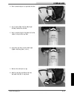
Drain and refill the hydraulic fluid reservoir with
new hydraulic fluid every 800 hours of operation.
NOTE: When the hydraulic filter bypass light
(optional) comes on, replace the filter, and change
the hydraulic fluid as soon as possible.
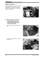
The hydraulic fluid filter is located in front of the
hydraulic reservoir near the rear of the engine
compartment. Replace the filter element every
800 hours of operation.
Summary of Contents for 6100 G/LP
Page 1: ...330235 Rev 02 9 01 Service Manual 6100 G LP ...
Page 4: ...GENERAL INFORMATION 1 2 6100 G LP 330235 9 01 ...
Page 18: ...CHASSIS 2 2 6100 G LP 330235 9 00 ...
Page 27: ...CHASSIS 2 11 6100 G LP 330235 9 00 7 Remove the hub assembly from the tire assembly ...
Page 72: ...CHASSIS 2 56 6100 G LP 330235 9 00 ...
Page 74: ...SWEEPING 3 2 6100 G LP 330235 9 00 ...
Page 152: ...ELECTRICAL 4 2 6100 G LP 330235 9 00 ...
Page 175: ...ELECTRICAL 4 25 6100 G LP 330235 9 01 ...
Page 176: ...ELECTRICAL 4 26 6100 G LP 330235 9 01 ELECTRICAL SCHEMATIC GAS 1 2 3 4 ...
Page 177: ...ELECTRICAL 4 27 6100 G LP 330235 9 01 ELECTRICAL SCHEMATIC GAS 1 2 3 4 ...
Page 178: ...ELECTRICAL 4 28 6100 G LP 330235 9 01 ELECTRICAL SCHEMATIC LP 1 2 3 4 ...
Page 179: ...ELECTRICAL 4 29 6100 G LP 330235 9 01 ELECTRICAL SCHEMATIC LP 1 2 3 4 ...
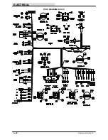
Page 180: ...ELECTRICAL 4 30 6100 G LP 330235 9 01 WIRE DIAGRAM GAS LP ...
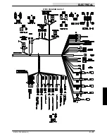
Page 181: ...ELECTRICAL 4 31 6100 G LP 330235 9 01 WIRE DIAGRAM GAS LP ...
Page 182: ...ELECTRICAL 4 32 6100 G LP 330235 9 01 ...
Page 190: ...ELECTRICAL 4 40 6100 G LP 330235 9 00 ...
Page 192: ...HYDRAULICS 5 2 6100 G LP 330235 9 00 ...
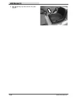
Page 198: ...HYDRAULICS 5 8 6100 G LP 330235 9 00 9 Disengage the prop rod and close the seat support ...
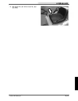
Page 205: ...HYDRAULICS 5 15 6100 G LP 330235 9 00 10 Disengage the seat rod and close the seat assembly ...
Page 217: ...HYDRAULICS 5 27 6100 G LP 330235 9 00 HYDRAULIC SCHEMATIC ...
Page 218: ...HYDRAULICS 5 28 6100 G LP 330235 9 00 OUT IN B A B A HYDRAULIC HOSE DIAGRAM ...
Page 220: ...HYDRAULICS 5 30 6100 G LP 330235 9 00 ...
Page 221: ......
Page 222: ......
Page 223: ......
Page 224: ......
Page 225: ......
Page 226: ......
Page 227: ......
Page 228: ......
Page 229: ......
Page 230: ......
Page 231: ......
Page 232: ......
Page 233: ......
Page 234: ......
Page 235: ......
Page 236: ......
Page 237: ......
Page 238: ......
Page 239: ......
Page 240: ......
Page 241: ......
Page 242: ......
Page 243: ......
Page 244: ......
Page 245: ......
Page 246: ......
Page 247: ......
Page 248: ......
Page 249: ......
Page 250: ......
Page 252: ...ENGINE GAS LP 6 2 6100 G LP 330235 9 00 ...

