HYDRAULICS
5-21
6200D 330395 (8--99)
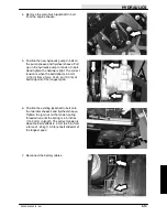
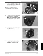
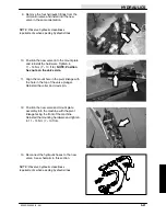
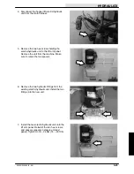
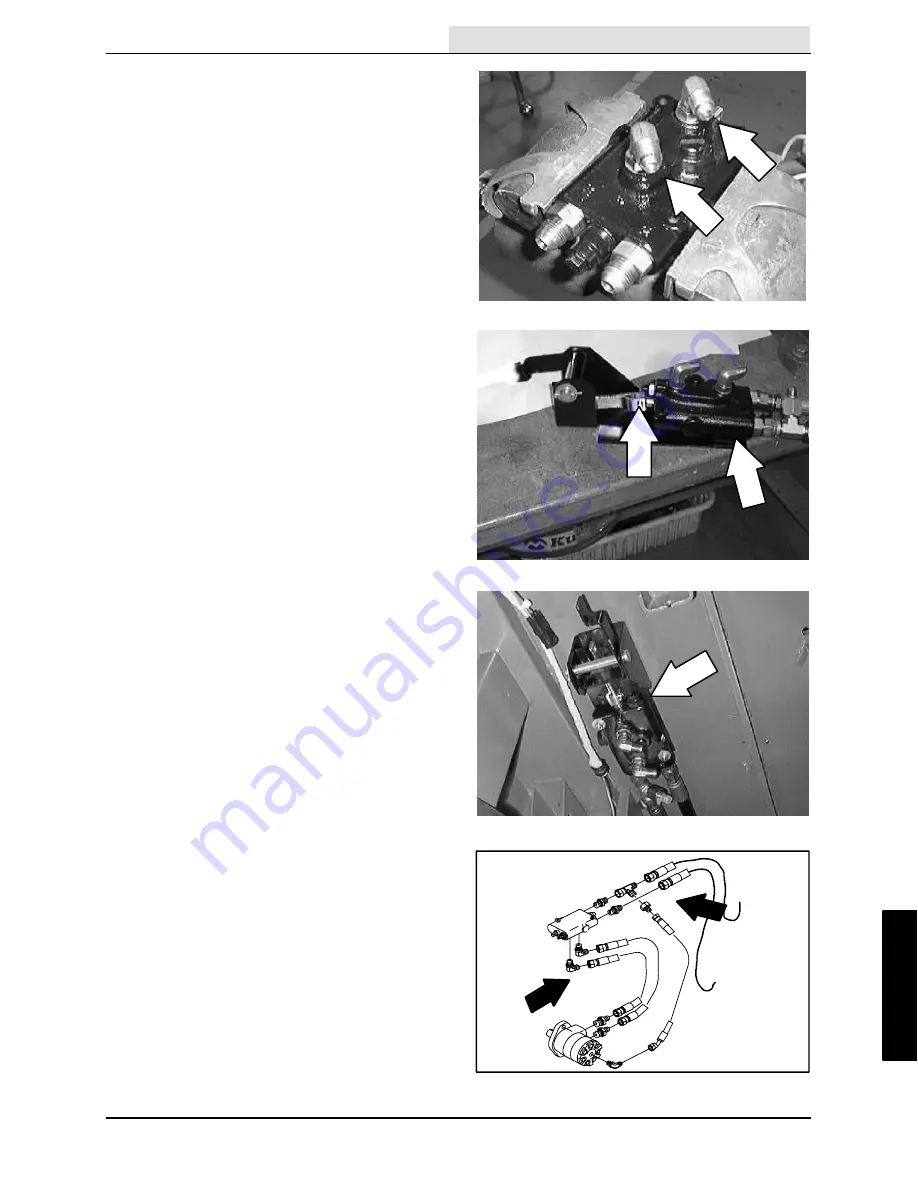
9. Remove the four hydraulic fittings from the
old control valve and install into the new
valve in the same orientation.
NOTE: Observe hydraulic cleanliness
requirements when opening hydraulic lines.
10. Position the new valve onto the mount plate
and reinstall the hardware. Tighten to
11 -- 14 Nm (7 -- 10 ft lb).
NOTE: Position
hex nuts on the valve side.
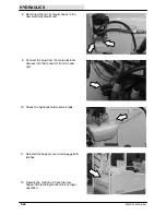
11. Align the mount hole in the pivot linkage with
the hole in the top of the valve plunger.
Reinstall the cotter and clevis pin.
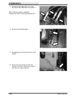
12. Position the new valve and mount plate
assembly into the machine with the pivot
linkage facing the front of the machine.
Reinstall the mounting hardware and tighten
to 11 -- 14 Nm (7 -- 10 ft lb).
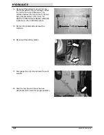
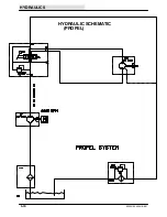
13. Reconnect the hydraulic hoses to the new
valve. See schematic in this section.
NOTE: Observe hydraulic cleanliness
requirements when opening hydraulic lines.
OUT
IN
B
A
B
A
Summary of Contents for 6200D
Page 1: ...330395 Rev 01 6 02 Service Manual 6200D 330395 ...
Page 4: ...GENERAL INFORMATION 1 2 6200D 330395 8 99 ...
Page 18: ...GENERAL INFORMATION 1 16 6200D 330395 8 99 ...
Page 20: ...CHASSIS 2 2 6200D 330395 8 99 ...
Page 74: ...CHASSIS 2 56 6200D 330395 8 99 ...
Page 76: ...SWEEPING 3 2 6200D 330395 8 99 ...
Page 138: ...SWEEPING 3 64 6200D 330395 6 02 ...
Page 140: ...ELECTRICAL 4 2 6200D 330395 8 99 ...
Page 176: ...ELECTRICAL 6200D 330395 6 02 4 38 ELECTRICAL SCHEMATIC 353188 D ...
Page 177: ...ELECTRICAL 4 39 6200D 330395 6 02 WIRE HARNESSES GROUP 352986 353189 D ...
Page 178: ...ELECTRICAL 6200D 330395 6 02 4 40 WIRE HARNESSES GROUP 352986 353189 D ...
Page 179: ...ELECTRICAL 4 41 6200D 330395 6 02 WIRE HARNESSES GROUP 352986 353189 D ...
Page 180: ...ELECTRICAL 6200D 330395 6 02 4 42 WIRE HARNESSES GROUP 352986 353189 D ...
Page 181: ...ELECTRICAL 4 43 6200D 330395 6 02 WIRE HARNESSES GROUP 352986 353189 D ...
Page 182: ...ELECTRICAL 6200D 330395 6 02 4 44 WIRE HARNESSES GROUP 352986 353189 D ...
Page 184: ...HYDRAULICS 5 2 6200D 330395 8 99 ...
Page 212: ...HYDRAULICS 5 30 6200D 330395 8 99 HYDRAULIC SCHEMATIC PROPEL ...
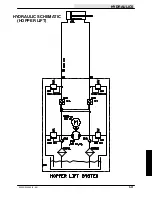
Page 213: ...HYDRAULICS 5 31 6200D 330395 8 99 HYDRAULIC SCHEMATIC HOPPER LIFT ...
Page 214: ...HYDRAULICS 5 32 6200D 330395 6 02 OUT IN B A B A 2 3 4 5 6 1 HYDRAULIC HOSE DIAGRAM PROPEL ...
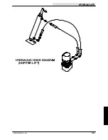
Page 215: ...HYDRAULICS 5 33 6200D 330395 6 02 HYDRAULIC HOSE DIAGRAM HOPPER LIFT ...
Page 220: ...2 2 General Purpose Motors ...
Page 227: ......
Page 228: ......
Page 229: ......
Page 230: ......
Page 248: ...ENGINE DIESEL 6 2 6200D 330395 8 99 ...

