7
Series 26 - Model 26000 Single Gear Pumps
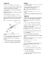
Reversibility
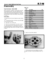
Changing Input Rotation of Pump
1
Place pump in a protected jaw vise with shaft end up.
Remove the eight cap screws.
2
Remove front plate, noting orientation of drive shaft
through bearing in reference to the backplate.
3
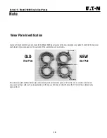
Notice the location of the open side of wear plate and
remove wear plate.
4
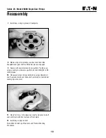
Switch
drive gear and idler gear within gear pockets. Do
not flip idler gear end for end.
Note: Gear housing body and backplate do not need altering.
5
Re-install wear plate into gear pockets over the gears with
seal and backup gasket up. (Same orientation as removed)
6
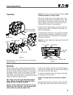
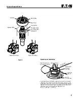
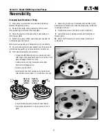
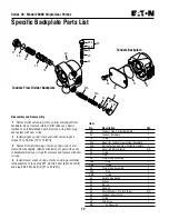
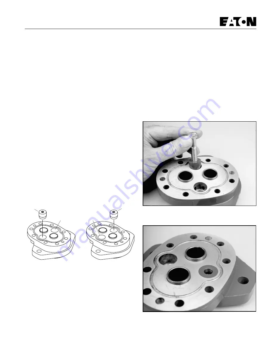
Front plate disassembly and assembly:
- Thread 3/8 UNC threaded bolt into
plug cavity. Start
with fingers, then place bolt head in vise and turn front
plate to engage threads 2-3 turns.
- Holding bolt in vise, tap front plate with rubber
hammer to disengage
plug.
- Remove
plug from bolt.
- Install plug in the other casting cavity and tap flush
with rubber hammer. Note L or R at bottom of cavity.
40
Plug
40
Plug
Open for
righthand
rotation
Open for
lefthand
rotation
R
L
R
L
- Ensure that bearing drain holes are free of debris.
- Note proper placement of o-ring in groove of front
plate.
7
Hold o-ring in groove of front plate with petroleum jelly.
Reassemble front plate over drive shaft end, being careful not
to damage shaft seal.
8
Torque 8 cap screws 34 to 38 N•m [25 to 28 lbf•ft].
9
Lubricate gears and mating surfaces with hydraulic oil
through ports.
10 Rotate shaft (manually) to ensure proper assembly of
components.
Summary of Contents for 6200D
Page 1: ...330395 Rev 01 6 02 Service Manual 6200D 330395 ...
Page 4: ...GENERAL INFORMATION 1 2 6200D 330395 8 99 ...
Page 18: ...GENERAL INFORMATION 1 16 6200D 330395 8 99 ...
Page 20: ...CHASSIS 2 2 6200D 330395 8 99 ...
Page 74: ...CHASSIS 2 56 6200D 330395 8 99 ...
Page 76: ...SWEEPING 3 2 6200D 330395 8 99 ...
Page 138: ...SWEEPING 3 64 6200D 330395 6 02 ...
Page 140: ...ELECTRICAL 4 2 6200D 330395 8 99 ...
Page 176: ...ELECTRICAL 6200D 330395 6 02 4 38 ELECTRICAL SCHEMATIC 353188 D ...
Page 177: ...ELECTRICAL 4 39 6200D 330395 6 02 WIRE HARNESSES GROUP 352986 353189 D ...
Page 178: ...ELECTRICAL 6200D 330395 6 02 4 40 WIRE HARNESSES GROUP 352986 353189 D ...
Page 179: ...ELECTRICAL 4 41 6200D 330395 6 02 WIRE HARNESSES GROUP 352986 353189 D ...
Page 180: ...ELECTRICAL 6200D 330395 6 02 4 42 WIRE HARNESSES GROUP 352986 353189 D ...
Page 181: ...ELECTRICAL 4 43 6200D 330395 6 02 WIRE HARNESSES GROUP 352986 353189 D ...
Page 182: ...ELECTRICAL 6200D 330395 6 02 4 44 WIRE HARNESSES GROUP 352986 353189 D ...
Page 184: ...HYDRAULICS 5 2 6200D 330395 8 99 ...
Page 212: ...HYDRAULICS 5 30 6200D 330395 8 99 HYDRAULIC SCHEMATIC PROPEL ...
Page 213: ...HYDRAULICS 5 31 6200D 330395 8 99 HYDRAULIC SCHEMATIC HOPPER LIFT ...
Page 214: ...HYDRAULICS 5 32 6200D 330395 6 02 OUT IN B A B A 2 3 4 5 6 1 HYDRAULIC HOSE DIAGRAM PROPEL ...
Page 215: ...HYDRAULICS 5 33 6200D 330395 6 02 HYDRAULIC HOSE DIAGRAM HOPPER LIFT ...
Page 220: ...2 2 General Purpose Motors ...
Page 227: ......
Page 228: ......
Page 229: ......
Page 230: ......
Page 248: ...ENGINE DIESEL 6 2 6200D 330395 8 99 ...

