Page 5 of 7
KIT NO. 9006309--5680, 9006310--5700/5700XP
5680/5700/5700XP
ec-H2O
Kit
INSTALLATION INSTRUCTIONS --
Continued
9005074 Rev. 01 (05--09)
Tennant Company
Customer Service: (800) 553--8033 or (763) 513--2850
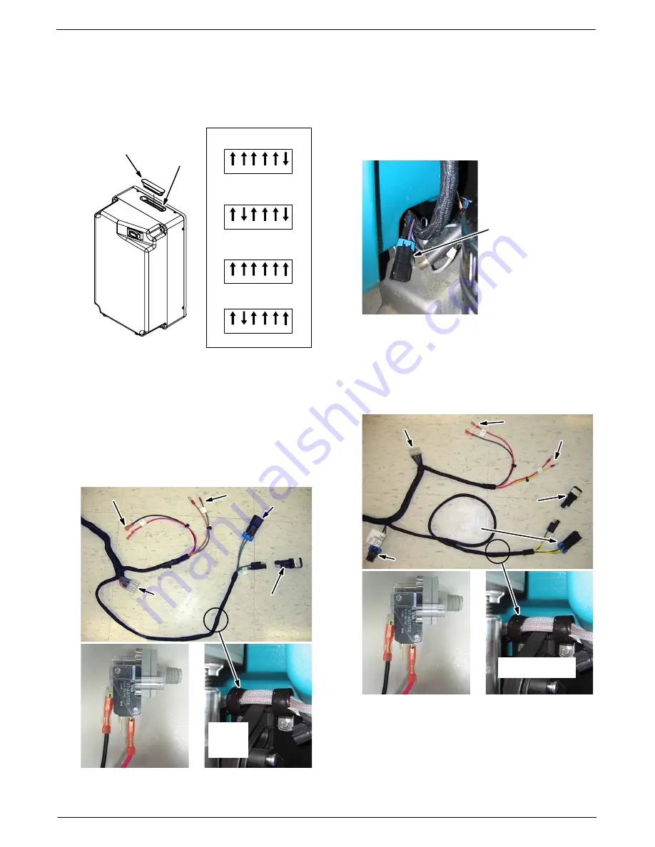
9. Set the module dip switches accordingly and
install grommet (Figure 19).
DIP
Switches
DIP Switch Setting
28”/700mm &
32”/800mm Disk Model
1 2 3 4 5 6
Grommet
[1050431]
28”/700mm &
32”/800mm Cyl Model
1 2 3 4 5 6
36”/900mm Disk Model
1 2 3 4 5 6
36”/900mm Cyl Model
1 2 3 4 5 6
Fig. 19
5680
MODEL -- CONNECT THE
ec- H2O
WIRE HARNESS TO KIT COMPONENTS:
1. Connect the routed
ec--H2O
wire harness to the
ec--H2O
components as indicated (Figure 20).
Route the pump wire connector through the two
hose clamps as indicated.
2. Connect the capacitor plug [p/n 1040868] to the
e--H2O
wire harness as shown (Figure 20).
To Pressure Switch
To Module
To Pump
Capacitor
Plug
1040868]
Pressure
Switch
Red
Blk
To Horn
Route
Harness
through
clamps
Fig. 20
3. Secure the
ec--H2O
wire harness to the machine
using the two wire--ties provided [p/n 130773].
5700/5700XP
MODEL -- CONNECT THE
ec-
H2O
WIRE HARNESS TO KIT COMPONENTS:
1. Locate the open plug connector on the main wire
harness near the scrub head (Figure 21).
Open plug connector
13A Black/27 Purple
from Main Wire
Harness
Fig. 21
2. Connect the routed
ec--H2O
wire harness to the
ec--H2O
components as indicated (Figure 22).
Route the pump wire connector through the two
hose clamps as indicated.
3. Connect the capacitor plug [p/n 1040868] to the
e--H2O
wire harness as shown (Figure 22).
To Module
To Pump
Pressure
Switch
Red
Blk
To Horn
Capacitor
Plug
[1040868]
To Pressure Switch
To Main Harness
Route Harness
through clamps
Fig. 22
4. Secure the
ec--H2O
wire harness to the machine
using the two wire--ties provided [p/n 130773].


