background image

OPERATION

13

S20 Gas/LP 9006719 (8

2009)

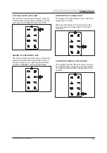
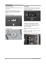
MAIN COVER LEVER

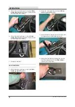
The main cover lever releases and locks the seat
support.

Release: Pull the lever back and lift the main
cover.

Lock: Close the main cover and release the lever
to lock the cover in place.

STEERING WHEEL TILT HANDLE

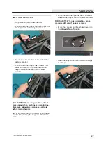
The steering wheel tilt handle controls the angle
of the steering wheel.

Adjust:  Pull out the tilt handle, move the steering
wheel up or down, and release the tilt handle.

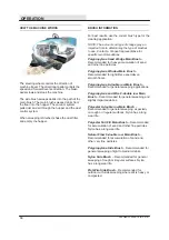
MAIN BRUSH ADJUSTMENT KNOB

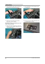
The main brush adjustment knob changes the
amount of contact the main brush has with the
surface being swept. Refer to 

ADJUSTING THE

MAIN BRUSH WIDTH 

section of this manual

.

NOTE: The main brush adjustment knob can be
repositioned if it interferes with any of the
controls. Lift the knob, turn it to the desired
position, and release it

.

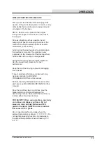
SIDE BRUSH ADJUSTMENT KNOB

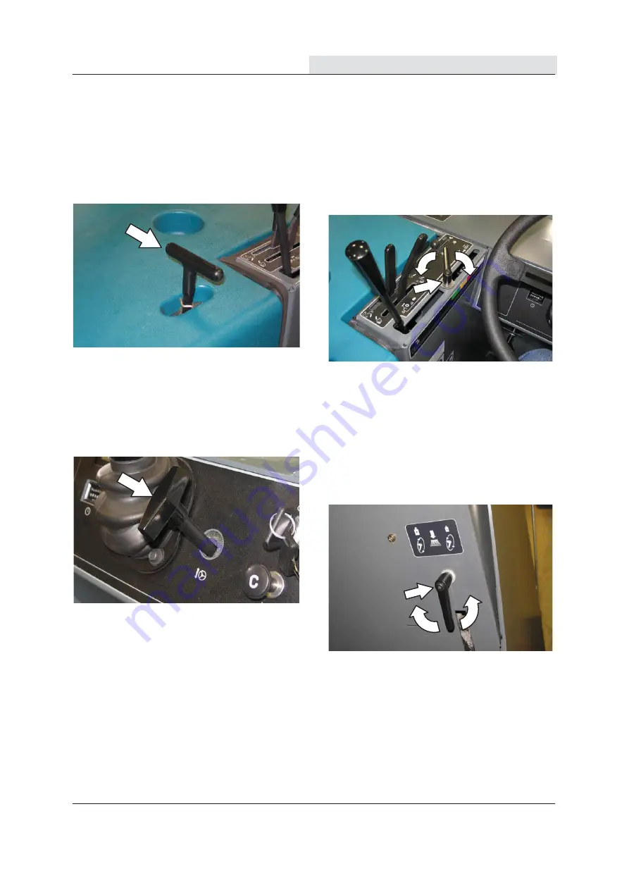
The side brush adjustment knob changes the
amount of contact the side brush has with the
surface being swept. Refer to 

ADJUSTING THE

SIDE BRUSH PATTERN 

section of this manual

.

NOTE: The side brush adjustment knob can be
repositioned. Lift the knob, turn it to the desired
position, and release it

.

Summary of Contents for GL20

Page 1: ...nt S20 Sweeper LPG OPERATOR MANUAL Clemas Co Unit 5 Ashchurch Business Centre Alexandra Way Tewkesbury Gloucestershire GL20 8NB Tel 01684 850777 Fax 01684 850707 Email info clemas co uk Web www clemas co uk ...

Page 2: ... sweep hard surfaces concrete asphalt stone synthetic etc Typical applications include industrial warehouses manufacturing facilities distribution facilities stadiums arenas convention centers parking facilities transportation terminals and construction sites Do not use this machine on soil grass artificial turf or carpeted surfaces This machine can be used both indoors and outdoors but ensure the...

Page 3: ...ting 34 Maintenance 35 Maintenance Chart 35 Lubrication 37 Engine Oil 37 Rear Wheel Support 37 Front Wheel Bearings 37 Hopper Lift Arm Pivots 37 Page Hydraulics 38 Hydraulic Fluid Reservoir 38 Hydraulic Fluid 39 Hydraulic Hoses 39 Engine 40 Cooling System 40 Air Filter Indicator 41 Air Filter 41 Engine Belt 42 Fuel Filter Gasoline 42 Fuel Filter Lpg 42 Carburetor 43 Spark Plugs 43 Valve Clearance ...

Page 4: ...hine 56 Pushing Or Towing The Machine 56 Transporting The Machine 56 Machine Jacking 58 Storage Information 58 Specifications 59 General Machine Dimensions Capacities 59 General Machine Performance 60 Power Type 60 Steering 60 Hydraulic System 60 Braking System 61 Tires 61 Machine Dimensions 61 Index 62 ...

Page 5: ...SAFETY PRECAUTIONS 3 S20 Gas LP 9006719 8 2009 ...

Page 6: ...one use is restricted because of concerns related to equipment interference please contact a Tennant representative for information on how to disable the cellular communication functionality FOR SAFETY 1 Do not operate machine Unless trained and authorized Unless operator manual is read and understood Under the influence of alcohol or drugs While using a cell phone or other types of electronic dev...

Page 7: ...trical components Disconnect battery connections before working on machine Avoid contact with battery acid Avoid contact with hot engine coolant Do not remove cap from radiator when engine is hot Allow engine to cool Keep flames and sparks away from fuel system service area Keep area well ventilated Use cardboard to locate leaking hydraulic fluid under pressure All repairs must be performed by tra...

Page 8: ...rator compartment Located on both hopper lift arms Located on engine belt guard 354902 Located only on machines with cab option WARNING LABEL Machine emits toxic gases Serious injury or death can result Provide adequate ventilation WARNING LABEL Machine can emit excessive noise Hearing loss can result Wear hearing protection WARNING LABEL Lift arm pinch point Stay clear of hopper lift arms WARNING...

Page 9: ...he hopper support bar Located on the optional vacuum wand 354902 WARNING LABEL Burn hazard Hot surface Do not touch WARNING LABEL Raised hopper may fall Engage hopper support pin FOR SAFETY LABEL Read manual before operating machine WARNING LABEL Raised hopper may fall Engage hopper support pin WARNING LABEL Accident may occur Do not operate vacuum wand while driving ...

Page 10: ... S20 Gas LP 9006719 8 2009 OPERATION MACHINE COMPONENTS 1 2 3 4 6 7 5 8 9 1 Operator seat 2 Steering wheel 3 Instrument panel 4 Hopper cover 5 Side brush 6 Brush door 7 Fuel tank 8 Hopper access door 9 Main cover ...

Page 11: ...11 Hopper temperature light Thermo Sentry 12 Clogged dust filter light 13 Engine water temperature light 14 Charging system light 15 LPG fuel level low light 16 Engine oil pressure light 17 Hopper door closed light 18 Clogged hydraulic filter light 19 Fuel level gauge 20 Hour meter 21 Steering wheel 22 Horn button 23 Steering wheel tilt handle 24 Ignition switch 25 Engine choke knob gasoline only ...

Page 12: ... Clogged dust filter Vacuum fan off Hopper door closed light Fast engine speed Clogged hydraulic filter Idle engine speed LPG fuel level low Hopper down Hourmeter Hopper up Steering wheel tilt Hopper door open Off Hopper door close lever On Main brush down and on Start Main brush up and off Horn Battery charging system Operating lights Engine oil pressure Hazard light ...

Page 13: ...09 Engine water temperature Side brush down and on Side brush up and off Side brush pressure Engine choke Gasoline Only Unleaded fuel only Parking brake Brush pressure Increase Brush pressure Decrease Turn counterclockwise Turn clockwise ...

Page 14: ...NG BRAKE PEDAL Press the Brake pedal down as far as possible and use toe to lock the Parking brake pedal into place Press the Brake pedal to release the parking brake The Parking brake pedal will return to the unlocked position NOTE If the operator is not in the seat the parking brake must be engaged or the machine will automatically shut off after 2 seconds PARKING BRAKE LIGHT The parking brake l...

Page 15: ...T KNOB The main brush adjustment knob changes the amount of contact the main brush has with the surface being swept Refer to ADJUSTING THE MAIN BRUSH WIDTH section of this manual NOTE The main brush adjustment knob can be repositioned if it interferes with any of the controls Lift the knob turn it to the desired position and release it SIDE BRUSH ADJUSTMENT KNOB The side brush adjustment knob chan...

Page 16: ... the hopper dust filter is clogged To clean the filter hold the vacuum and filter shaker lever in the Filter shaker position If the clogged dust filter light remains lit manually clean the hopper dust filter See HOPPER DUST FILTER in the MAINTENANCE section of this manual NOTE The clogged dust filter light also comes on when the hopper door is closed and the vacuum fan is on HOPPER TEMPERATURE LIG...

Page 17: ...below 40 kPa 5 psi If the light comes on stop operating the machine Contact a TENNANT service representative HOPPER DOOR CLOSED LIGHT The hopper door closed light comes on when the hopper door is closed Make sure the hopper door is open all the way and the hopper door closed light is off before sweeping CLOGGED HYDRAULIC FILTER LIGHT The clogged hydraulic filter light comes on when the hydraulic f...

Page 18: ... level gauge LP tank level gauge HOUR METER The Hour meter records the hours the machine was operated Use this information to determine machine service intervals OPERATING HAZARD LIGHTS SWITCH The operating hazard lights switch powers on and off the headlights and taillights and the optional hazard light Operating lights on Press the top part of the switch Operating Hazard lights on Optional Press...

Page 19: ...operator weight and front to back The operator s weight adjustment lever controls the seat weight adjustment The lever has three positions lightweight middleweight and heavyweight The backrest adjustment knob adjusts the angle of the backrest The front to back adjustment lever adjusts the seat position SEAT BELTS OPTION FOR SAFETY Before starting machine adjust seat and fasten seat belt if equippe...

Page 20: ... Recommended for heavy accumulation of sand and other fine particles Polypropylene Window Main Brush Recommended for light litter especially on smooth floors Polypropylene 8 double row Main Brush Recommended for general sweeping applications Polypropylene and Wire 8 double row Main Brush Recommended for general sweeping and slightly impacted debris Polyester 8 double row Main Brush Recommended for...

Page 21: ... the machine speed and brush pressure Use the lowest brush pressure for best performance Keep the machine moving to prevent damaging floor finishes If poor cleaning performance is observed stop cleaning and refer to MACHINE TROUBLESHOOTING in this manual Perform the Daily Maintenance Procedures after each use see MACHINE MAINTENANCE in this manual Drive the machine slowly on inclines Use the brake...

Page 22: ... Check the main brush compartment left skirt for damage and wear Check the air filter indicator Check the engine oil level Check the engine coolant level Check the radiator fins and cooling fan screen for debris Check the hydraulic fluid level Check for rubbing hoses or wires and leaks or obstructions Check the horn headlights taillights safety lights and backup alarm if equipped Check all control...

Page 23: ...way from fuel system service area Keep area well ventilated 4 Put on gloves and remove the quick disconnect tank coupling 350412 5 Unlatch and remove the empty LPG fuel tank from the machine 6 Carefully put the filled LPG tank in the machine so that the tank centering pin enters the aligning hole in the tank collar 350412 7 Fasten the tank hold down clamp to lock the tank in position 8 Connect the...

Page 24: ...kes with the directional pedal in neutral FOR SAFETY When starting machine keep foot on brake and directional pedal in neutral 3 Move the throttle lever back into the Idle engine speed position 4 On gasoline powered machines pull out the choke knob when the engine is cold Push in the choke knob after the engine is running smoothly 5 Turn the ignition switch key clockwise until the engine starts NO...

Page 25: ...vere respiratory damage or asphyxiation can result Provide adequate ventilation Consult with your regulatory authorities for exposure limits Keep engine properly tuned 7 Turn on lights 8 Move the throttle lever all the way forward into the Fast engine speed position 9 Release the machine parking brake 10 Drive the machine to the area to be cleaned ...

Page 26: ...ngine speed position 4 Set the machine parking brake 5 Turn the ignition switch key counterclockwise to stop the machine Remove the switch key FOR SAFETY Before leaving or servicing machine do not park near combustible materials dust gases or liquids Stop on level surface set parking brake turn off machine and remove key 6 LPG powered machines Close the LPG tank s liquid service valve 350412 ...

Page 27: ...reduce performance 3 Push the hopper door lever forward to open the hopper door 4 Move the vacuum and filter shaker lever to the Vacuum fan on position NOTE The vacuum fan duct should be off when sweeping wet debris NOTE Excessive heat in the hopper will cause the Thermo Sentry to move the vacuum and filter shaker lever to the Vacuum fan off position It will also make the hopper temperature light ...

Page 28: ...tion The brush will automatically start rotating 7 Sweep as needed STOP SWEEPING 1 Place the side brush lever in the right Side brush up and off position 2 Place the main brush lever in the left Main brush up and off position 3 Pull and hold the hopper door lever back until the hopper door closed light comes on 4 Shake the dust filter by holding the vacuum and filter shaker lever in the Filter sha...

Page 29: ...r into the Hold position FOR SAFETY When using machine do not raise hopper when machine is on an incline Make sure adequate clearance is available before raising hopper NOTE Be aware that the minimum ceiling height needed to high dump the hopper is 2490 mm 98 in 5 Drive the machine up to the debris container Position the hopper over the debris container FOR SAFETY When using machine move machine w...

Page 30: ...y from the debris site or debris container FOR SAFETY When using machine use care when reversing machine 10 Push and hold the hopper raise lower lever forward to lower the hopper Release the lever into the Hold position 11 Push the hopper door lever forward to open the hopper door 12 Move the vacuum and filter shaker lever into the Vacuum fan on position ...

Page 31: ...gine speed position 4 Pull and hold the hopper raise lower lever back and raise the hopper to the desired height Release the lever into the Hold position FOR SAFETY When using machine make sure adequate clearance is available before raising hopper NOTE Be aware that the minimum ceiling height needed to high dump the hopper is 2490 mm 98 in 5 Lower and position the hopper support bar onto the suppo...

Page 32: ...er back into the Idle engine speed position 8 Shut the machine off DISENGAGING HOPPER SUPPORT BAR 1 Start the machine FOR SAFETY When starting machine keep foot on brake and directional pedal in neutral 2 Move the throttle lever all the way forward into the Fast engine speed position 3 Pull and hold the hopper raise lower lever back and raise the hopper slightly Release the lever into the Hold pos...

Page 33: ...osition WARNING Lift arm pinch point Stay clear of hopper lift arms 5 Push and hold the hopper raise lower lever forward to lower the hopper Release the hopper lever into the Hold position 6 Move the throttle lever back into the Idle engine speed position 7 Shut the machine off ...

Page 34: ... the operator is not in the seat the parking brake must be engaged or the machine will automatically shut off after 2 seconds 3 Open the hopper cover and prop the cover open 4 Remove the vacuum wand from the mounting clips and the hose from the storage compartment 5 Connect the vacuum hose to the vacuum wand 6 Open the access door located at the front of the machine 7 Connect the other end of the ...

Page 35: ...tion to open the hopper door 14 Shut the machine off 15 Remove the vacuum hose from the hopper connection 16 Close the access door 17 Disconnect the vacuum hose from the vacuum wand 18 Put the vacuum wand in the mounting clips and the hose into the storage compartment 19 Close the hopper cover TOWER BUMPERS OPTION The tower bumpers help protect the machine from being damaged Open the tower bumpers...

Page 36: ...ailure Ensure Thermo Sentry wires are connected Contact TENNANT service per sonnel Thermo Sentry tripped Allow Thermo Sentry to cool Poor sweeping performance Brush bristles worn Replace brushes Main and side brushes not adjusted properly Adjust main and side brushes Debris caught in main brush drive mechanism Remove debris from the drive mechanism Hopper door partially or completely closed Open h...

Page 37: ... Main brush compart ment skirts Check for damage wear and adjustment All O 12 Hopper lip skirts Check for damage wear and adjustment 3 O 9 Main brush Check for damage or wear 1 O 11 Side brush es Check for damage or wear 1 O 10 Hopper dust filter Shake 1 O 15 Hydraulic fluid reservoir Check fluid level HYDO 1 50 Hours O 9 Main brush Rotate end for end 1 T 9 Main brush Check brush pattern and ad ju...

Page 38: ...T 15 Hydraulic fluid reservoir Replace filler cap 1 Replace suction strainer 1 T 16 Hydraulic fluid filter Change filter element All T Hydraulic hoses Check for wear and damage All T 17 Propelling motor Torque shaft nut 1 T 3 Rear wheel Torque wheel nuts 1 T 5 Battery Clean and tighten battery cable connections 1 T 4 Engine Replace fuel filter 1 Check valve clearance 1 T 1 Cooling system Flush WG ...

Page 39: ...eration Fill the engine with oil until the oil is between the indicator marks on the dipstick DO NOT fill past the top indicator mark The engine oil capacity is 3 4 L 3 6 qt with oil filter REAR WHEEL SUPPORT Lubricate the rear wheel support bearings after every 200 hours of operation FRONT WHEEL BEARINGS Repack and adjust the front wheel bearings every 400 hours of operation HOPPER LIFT ARM PIVOT...

Page 40: ...r Damage to the machine hydraulic system may result Drain and refill the hydraulic fluid reservoir with new TennantTrue premium hydraulic fluid after every 2400 hours of operation Machines have a blue colored drop left photo on the hydraulic fluid label if originally equipped with TennantTrue premium hydraulic fluid TennantTrue Fluid Previous Fluid NOTE Change the hydraulic fluid filter and suctio...

Page 41: ...e the specifications match the Tennant hydraulic fluid specifications Substitute fluids can cause premature failure of hydraulic components ATTENTION Hydraulic components depend on system hydraulic fluid for internal lubrication Malfunctions accelerated wear and damage will result if dirt or other contaminants enter the hydraulic system HYDRAULIC HOSES Check the hydraulic hoses after every 800 hou...

Page 42: ...ctions Check the radiator hoses and clamps after every 200 hours of operation Tighten loose clamps Replace damaged hoses and clamps Check the radiator core exterior and hydraulic cooler fins for debris daily Blow or rinse with low pressure air or water all dust through the grill and radiator fins the opposite direction of normal air flow Be careful to not bend the cooling fins when cleaning Clean ...

Page 43: ...ce set parking brake turn off machine and remove key The engine air filter housing is located in front of the engine compartment under the lintel Replace the air filter element when the air filter indicator shows restriction in the air intake system or the filter element is damaged Refer to AIR FILTER INDICATOR To remove the filter element raise the hopper and engage the hopper support bar Set the...

Page 44: ...an Keep away FUEL FILTER GASOLINE The fuel filter traps fuel contaminants The filter is located on the fuel line near the fuel pump FOR SAFETY When servicing machine keep flames and sparks away from fuel system service area Keep area well ventilated Replace the fuel filter after every 800 hours of operation FUEL FILTER LPG NOTE Close the LPG tank service valve and operate the engine until it stops...

Page 45: ...ance to 0 135 to 0 165 mm 0 0053 to 0 0064 in while the engine is cold after every 800 hours of operation VACUUM FAN BELT Check the vacuum fan belt tension and wear after every 200 hours of operation The correct tension is when the belt deflects 4 mm 0 16 in from a force of 0 7 kg 1 5 lb at belt midpoint BATTERY Clean and tighten the battery connections after the first 50 hours of operation and af...

Page 46: ...FU2 15 A Engine Instrumentation FU3 20 A Shaker Instrumentation FU4 15 A Lights FU5 15 A Horn FU6 5 A Windshield Wiper Optional FU7 15 A Turn Signals Optional FU8 15A Extra FU9 15A Extra FU10 5 A Cab Fan Optional FU11 15 A Telemetry FU12 Not Used FU13 Not Used FU14 Not Used FU15 Not Used FU16 Not Used FU17 Not Used FU18 Not Used FU19 Not Used FU20 Not Used NOTE Always replace a fuse with a fuse of...

Page 47: ...the filter after every 100 hours of operation Replace damaged dust filters NOTE Clean the filter more often if used in extremely dusty conditions 1 Unlatch and open the hopper cover Support the hopper cover open with the hopper cover prop rod 2 Remove the dust filter cover 3 Remove the dust filter from the hopper 4 Clean or discard the dust filter element Refer to CLEANING THE DUST FILTER 5 Clean ...

Page 48: ...r and out toward the exterior Never use more than 550 kPa 80 psi of air pressure with a nozzle no smaller than 3 mm 0 13 in and never hold the nozzle closer than 50 mm 2 in to the filter CLEANING THE CYCLONE ASSEMBLY FOR SAFETY Before leaving or servicing machine stop on level surface set parking brake turn off machine and remove key Clean the cyclones and filter housing after every 100 hours of o...

Page 49: ...rma filter for damage every 100 hours of operation CYCLONE COVER SEALS Check the cyclone cover seals for wear or damage every 100 hours of operation Clean dust and debris from the cyclones as necessary HOPPER DUST FILTER COVER SEAL Check the hopper dust filter cover seal for wear or damage every 100 hours of operation Clean dust and debris from the seal as necessary ...

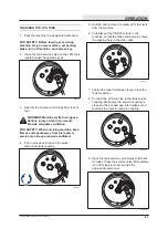
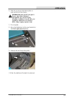
Page 50: ...sweeping performance Refer to REPLACING OR ROTATING THE MAIN BRUSH Replace the brush when it no longer cleans effectively REPLACING OR ROTATING THE MAIN BRUSH 1 Raise the brush head 2 Open the right side main brush access door 3 Loosen the brush idler plate T bolt Remove the brush idler arm assembly 4 Pull the main brush from the main brush compartment 5 Replace or rotate the main brush end for en...

Page 51: ...sh Refer to ADJUSTING THE MAIN BRUSH WIDTH 00582 FOR SAFETY Before leaving or servicing machine stop on level surface set parking brake turn off machine and remove key 4 If the brush pattern is tapered see ADJUSTING THE MAIN BRUSH TAPER section of this manual 00601 ADJUSTING THE MAIN BRUSH TAPER FOR SAFETY Before leaving or servicing machine stop on level surface set parking brake turn off machine...

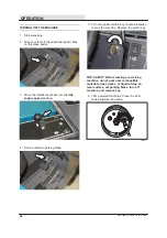
Page 52: ...ce the brush es when it no longer cleans effectively REPLACING THE SIDE BRUSH 1 Stop the machine set the parking brake and turn the engine off FOR SAFETY Before leaving or servicing machine stop on level surface set parking brake turn off machine and remove key 2 Remove the side brush retaining pin from the side brush drive shaft by pulling the pin keeper off over the end of the pin 08019 3 Slide ...

Page 53: ...brush pressure and clockwise to decrease the brush pressure SIDE BRUSH GUARD Rotate the side brush guard 90_ after every 200 hours of operation or sooner if worn Replace the brush guard after using all four sides SIDE BRUSH PIVOT The side brush pivot should be checked for excessive movement after every 200 hours of operation The side brush side tilt left to right is adjusted with the two bolts The...

Page 54: ... 3 mm 0 12 in Check the hopper side skirt for wear or damage and adjustment daily BRUSH DOOR SKIRTS The brush door skirts are located on the bottom of each of the two main brush doors The skirt should clear the floor by 3 mm 0 12 in Check the skirts for wear or damage and adjustment daily NOTE The brush door skirts have slotted holes to allow for a ground clearance adjustment Adjust the skirt heig...

Page 55: ... both main brush doors and on corresponding portions of the main frame Check the seals for wear or damage after every 100 hours of operation HOPPER SEALS The hopper seals are located on the top and side portions of the hopper Check the seals for wear or damage after every 100 hours of operation HOPPER ACCESS DOOR SEAL The hopper access door seal is located on the hopper and seals the front of the ...

Page 56: ...ebris hopper Check the seal for wear or damage after every 100 hours of operation HOPPER DOOR SEALS The hopper door seals are located on the hopper door They seal the hopper when the hopper door is closed Check the seals for wear or damage after every 100 hours of operation FILTER CHAMBER INLET SEAL Check the filter chamber inlet seal for wear or damage every 100 hours of operation ...

Page 57: ...5 in and 25 mm 1 0 in Adjust the brakes if required TIRES The standard front machine tires are solid The standard rear machine tire is pneumatic Check the front tires after every 100 hours of operation for damage Check the rear tire pressure after every 100 hours of operation The proper tire pressure is 795 kPa 115 psi REAR WHEEL Torque the rear wheel nuts twice in the pattern shown to 122 to 155 ...

Page 58: ...the normal position before pushing or towing the machine The illustration shows the bypass valve in the pushing or towing position Return the bypass valve to the normal position when through pushing or towing the machine TRANSPORTING THE MACHINE 1 Position the machine at the loading edge of the truck or trailer FOR SAFETY When loading machine onto truck or trailer empty hopper before loading machi...

Page 59: ...he machine tires Tie down the machine to the truck or trailer before transporting The front tie down locations are the holes in the wheel pockets at the front of the machine frame The rear tie down locations are the holes in the sides of the machine frame near the rear bumper 7 If the loading surface is not horizontal or is higher than 380 mm 15 in from the ground use a winch to unload machine If ...

Page 60: ...e block machine tires before jacking machine up Use a hoist or jack that will support the weight of the machine Jack machine up at designated locations only Support machine with jack stands The rear jacking location is the center of the rear bumper behind the back tire Front jacking locations are located on the frame directly in front of the front tire STORAGE INFORMATION The following steps shoul...

Page 61: ... 50 in Sweeping path width with dual side brushes 1575 mm 62 in Main sweeping brush pattern width 50 to 75 mm 2 to 3 in Hopper weight capacity polyethylene hopper 340 kg 750 lb Hopper weight capacity optional steel hopper 318 kg 700 lb Hopper volume capacity polyethylene hopper 310 L 11 ft3 Hopper volume capacityv optional steel hopper 319 L 11 25 ft3 Dust filter area 7 4 m2 80 ft2 Minimum ceiling...

Page 62: ...em Gasoline 87 octane minimum unleaded Alternative Ethanol no greater than E 10 blend Fuel tank 27 6 L 7 3 gal Water ethylene glycol antifreeze 12 V nominal LPG Fuel tank 15 kg 33 lb Total 8 L 2 gal 40 A alternator Radiator 4 L 1 gal Idle speed Fast governed speed Firing order 1350 50 rpm 2500 50 rpm 1 2 3 Spark plug gap Valve clearance cold Engine lubricating oil with filter 1 mm 0 043 in 0 135 t...

Page 63: ... actuated Parking brake Utilize service brakes rod actuated TIRES Location Type Size Pressure Front 2 Solid 89 x 410 mm 3 5 X 16 in Rear 1 Pnuematic 150 x 410 mm 6 X 16 in 795 kPa 115 psi MACHINE DIMENSIONS TOP VIEW SIDE VIEW 2090 mm 82 3 in 1230 mm 48 5 in 2085 mm 82 1 in FRONT VIEW 1260 mm 49 5 in 1135 mm 44 7 in 1085 mm 42 7 in 354901 ...

Page 64: ...ght 14 Clogged dust filter light 14 Clogged hydraulic filter light 15 Engine oil pressure 15 Engine water temperature light 14 Fuel level gauge 16 Hopper door closed light 15 Hopper temperature light 14 LPG fuel level low light 15 Operating hazard lights switch 16 Parking brake light 12 Controls Charging system light 14 Clogged dust filter light 14 Clogged hydraulic filter light 15 Engine oil pres...

Page 65: ...s Fuel level 16 General Machine Dimensions Capacities 59 Grease fittings Hopper lift arm pivots 37 Rear Wheel Support Bearing 37 H Hopper Access door seal 53 Clogged dust filter Light 14 Disengaging hopper support bar 30 32 Door closed Light 15 Door seals 54 Emptying the hopper 27 29 Engaging hopper support bar 29 31 Inner access door seal 54 Lift arm pivots 37 Lip skirt 52 Seals 53 Side skirt 52 ...

Page 66: ...or seals 53 Door skirts 52 Rear skirts 52 Main brush adjustment knob 13 Main Brushes 48 Adjusting the Taper 49 Adjusting the Width 50 Replacing or Rotating the Main Brushes 48 Main Brushes Adjusting the Taper 49 Main Brushes Adjusting the Width 50 Main Brushes Replacing or Rotating 48 Main cover Lever 13 Main cover lever 13 Maintenance 35 59 Maintenance Chart 35 O Operating temperature 19 Operatin...

Page 67: ...ustment 13 Dust control skirts 53 Guard 51 Pivot 51 Replacing the Side Brush 50 Side brush down pressure knob 13 Side brush dust control skirts 53 Side brush guard 51 Side brush pivot 51 Side Brush Adjusting 51 Side Brush Replacing 50 Side brush es Checking brush pattern 51 Skirts 52 55 Brush doors 52 Hopper Lip 52 Hopper side 52 Rear 52 Side brush dust control 53 Spark plugs 43 Specifications 59 ...

Page 68: ...INDEX 66 S20 Gas LP 9006719 4 2014 V Vacuum fan Belt 43 Vacuum fan belt 43 Vacuum Wand 32 Valve clearance 43 Valves 43 Intake and exhaust 43 W Wheels 55 While operating the machine 19 ...

Reviews: