64
T380AMR 9020999 (08-2020)
MAINTENANCE
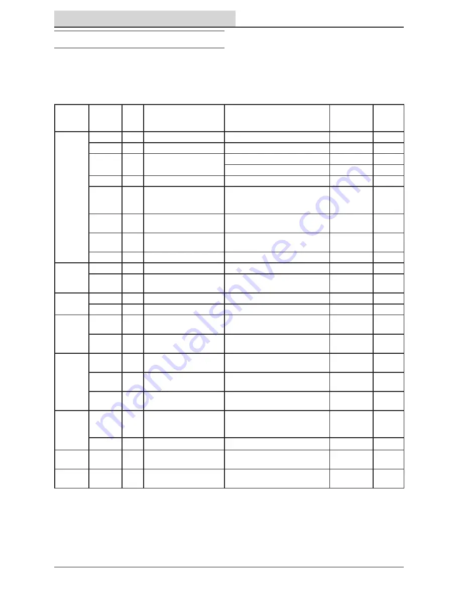
MAINTENANCE CHART
The table below indicates the Person Responsible
for each procedure.
O = Operator.
T = Trained Personnel.
Interval
Person
Resp.
Key
Description
Procedure
Lubricant/
Fluid
No. of
Service
Points
Daily
O
3
Pad
Check,
fl
ip or replace
1
O
3
Scrub brush
Check for damage, wear, debris
1
O
1
Squeegee
Check,
fl
ip or replace
-
3
Check de
fl
ection and leveling
-
6
O
8
Scrub head
fl
oor skirt
Check for damage and wear
1
O
2
Front/side 2D and 3D
sensors and upper/
lower LIDAR sensors
Check for damage. Clean with
provided micro
fi
ber cloth
-
8
O
4
Perimeter guards (left,
right, and front)
Check for debris, damage, and
wear
-
3
O
5
Recovery tank
Clean tank, screen
fi
lter, basket,
vacuum hose, and
fl
oat sensor
-
5
O
6
Solution tank
Drain and rinse as necessary
-
1
Weekly
O
7
Battery cells
Check electrolyte level
DW
18
T
4
Front perimeter guard
Inspect adjustment plates for
slipping. Adjust as necessary
1
50 Hours
O
5
Recovery tank lid seal
Check for wear and damage
1
O
15
Solution tank in-line
fi
lter Remove and clean
-
1
100
Hours
T
9
Vacuum fan seal and
squeegee seal
Check for damage and wear
-
2
O
7
Battery watering system
(option)
Check hoses for damage and
wear
-
All
200
Hours
T
7
Battery terminals and
cables
Check and clean
-
12
T
13
Steering gear chain
Lubricate, check tension, and
check for damage and wear.
GL
1
T
14
Steering u-joint
Lubricate and check for damage
and wear.
GL
1
500
Hours
T
11
Propelling motor
Check carbon brushes
(Check every 100 hours after
initial 500 hour check)
-
1
O
12
Tires
Check for damage and wear
-
3
750
Hours
T
9
Vacuum fan motor(s)
Replace carbon brushes
-
1
1250
Hours
T
10
Scrub brush motors
Replace carbon brushes
-
1
LUBRICANT/FLUID
DW Distilled
water
GL
SAE 90 weight gear lubricant


