background image

79

T380AMR 9020999 (08-2020)

 MAINTENANCE   

SQUEEGEE SEAL
FOR SAFETY: Before leaving or servicing 
machine, stop on level surface, turn off 
machine, and remove key.

Check the squeegee seal for damage and wear 
after every 100 hours of operation.

PERIMETER GUARDS
FOR SAFETY: Before leaving or servicing 
machine, stop on level surface, turn off 
machine, and remove key.

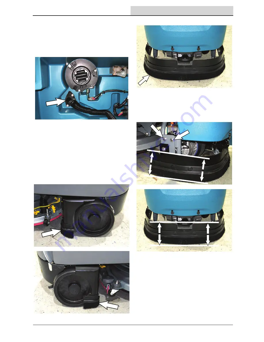
Check perimeter guard bristles for debris, damage, 
and wear daily. The bristles should lightly touch 
the 

fl

 oor. Replace damaged and/or worn bristle 

assemblies.

Left and right perimeter guards.

Front perimeter guard.

Inspect front perimeter guard adjustment plates 
located on both sides of the perimeter guard for 
slipping weekly. The entire top edge of the front 
perimeter guard must be parallel with the 

fl

 oor. 

Adjust the adjustment plates as necessary.

Summary of Contents for T380AMR

Page 1: ...Manual 9020999 Rev 00 08 2020 9020999 North America International For the latest Parts Manuals and other language Operator Manuals visit www tennantco com manuals Hygenic Fully Cleanable Tanks Tennan...
Page 2: ...MENT Please dispose of packaging materials used components such as batteries and fluids in an environmentally safe way according to local waste disposal regulations Always remember to recycle Model No...

Page 3: ...ned operators in controlled restricted environments approved by Brain Corp Tennant Company Additional training materials may be provided as to the intended use of the T380AMR Scrubber and it should on...

Page 4: ...Operating The Machine Robotic Mode Only 26 Scrubbing Manual Mode 27 Double Scrubbing 29 Water Pickup Mode No Scrubbing 30 Scrubbing Robotic Mode 31 Establish Home Location Codes 31 Logging Into BrainO...

Page 5: ...78 Recovery Tank Seal 78 Vacuum Fan Seal 78 Squeegee Seal 79 Perimeter Guards 79 Tires 80 Pushing Towing And Transporting The Machine 80 Pushing Or Towing The Machine 80 Transporting The Machine 81 Ja...

Page 6: ...instructions With brake disabled Without filters in place or with clogged filters If it is not in proper operating condition In areas where flammable vapors liquids or combustible dusts are present I...

Page 7: ...or cleaning practices Follow site safety guidelines concerning wet floors 5 Before leaving or servicing machine Stop on level surface Turn off machine and remove key 6 When servicing machine All work...

Page 8: ...ctive dust mask 7 When loading unloading machine onto off truck or trailer Use ramp truck or trailer that will support the weight of the machine and operator Drain tanks before loading machine Do not...

Page 9: ...perating machine Located on front electrical access panel WARNING LABEL Flammable materials can cause explosion or fire Do not use flammable materials in tank Located on solution tank near solution ta...

Page 10: ...hydrogen gas Explosion or fire can result Keep sparks and open flame away Keep covers open when charging Located on bottom of recovery tank Located on top of scrub head WARNING LABEL Spinning brush Ke...

Page 11: ...Recovery tank drain hose H Solution tank fill cap I Solution tank drain hose J Solution tank K Right perimeter guard L Recovery tank M Recovery tank cover N Flashing light O Operator seat P Retractabl...

Page 12: ...button D Horn button E Brush pressure button F Brush pressure indicator lights G Solution flow indicator lights H Solution flow button I Vacuum fan squeegee button J ec H2O system indicator light opt...

Page 13: ...SORS A Sensors Upper LIDAR B Signal lights Front C Sensors Front 2D camera D Sensors Front 3D camera E Sensors Side 2D camera located on each side of machine F Sensors Side 3D camera located on each s...

Page 14: ...ight side of the machine to access the squeegee carriage 3 Align the squeegee carriage pins into the squeegee assembly bracket 4 Slide the squeegee assembly onto the squeegee carriage until both squee...

Page 15: ...ad and lift the brush up onto the scrub head until the magnet in the scrub head secures the brush WARNING Magnetic Field Hazard Magnetic pad driver brush can be harmful to those with pacemakers or med...

Page 16: ...ll blink green red when it is time to replace cartridge FILLING THE SOLUTION TANK FOR SAFETY Before leaving or servicing machine stop on level surface turn off machine and remove key The machine is eq...

Page 17: ...l scrubbing Then set the preferred brush pressure and solution flow settings NOTE The machine does not save solution flow and brush pressure settings for a robotic route as cleaning needs may change A...

Page 18: ...n flow level should be set to a higher setting middle or top lights Travel speed and floor conditions will affect scrubbing performance With the 1 Step button activated press the Solution flow button...

Page 19: ...he machine clockwise to disengage the emergency stop function The Emergency Stop Button Released screen appears on the UI touchscreen immediately after the Emergency Stop button is disengaged Touch CO...

Page 20: ...a blue start pause button on the back that is used to start a robotic route or pause an in process robotic route When a saved navigation route is selected on the UI touchscreen the blue start pause b...

Page 21: ...nOS software and use its robotic functionality BATTERY DISCHARGE BAR The battery discharge bar displays the charge level of the batteries When the batteries are fully charged the battery discharge bar...

Page 22: ...o the ROC If the indicator is gray the ROC is not connected and cannot be paired with a cell phone Connected Not Connected BRAINOS SOFTWARE UPDATES Over the air updates allow new versions of BrainOS s...

Page 23: ...n allows an operator to teach a new cleaning route run an existing cleaning route robotically access triggered alert messages and more It also provides constant visibility to current battery life and...

Page 24: ...of floor finish to prepare the floor for recoating Scrubbing pad Blue For medium to heavy duty scrubbing Removes dirt spills and scuffs Buffing pad Red For light duty scrubbing without removing floor...

Page 25: ...s damage and wear F Check the vacuum hose for debris or blockage F Drain and clean the recovery tank F Check the brakes and steering for proper operation F Check the service records to determine maint...

Page 26: ...hine is operating and people are present in accordance with standard floor cleaning practices Follow site safety guidelines concerning wet floors See Autonomous Navigation Software End User License Ag...

Page 27: ...ergents restorers may cause failure to the ec H2O solution system Drain rinse and refill solution tank with cool clean water before operating the ec H2O system 4 Place the directional switch in the di...

Page 28: ...be used to control the machine if quicker stopping is needed or if operating on an incline Do not operate machine on inclines exceeding 7 when scrubbing FOR SAFETY When using machine in manual mode go...

Page 29: ...turn off the squeegee will raise and the vacuum fan will stop operating Then scrub the area Let the cleaning solution set on the floor for 3 5 minutes Before scrubbing the floor a second time loosen...

Page 30: ...k to make sure that the 1 Step button is not activated The light in the 1 Step button must be off WARNING Flammable materials or reactive metals can cause an explosion or fire Do not pick up Then pres...

Page 31: ...pped areas where more than six cleaning routes are needed Establish a unique home location code for each floor of a multi level building Install home location codes in a permanent location on an open...

Page 32: ...personnel can access and use the BrainOS robotic functionality 1 Turn the ON OFF key switch on Allow the BrainOS to start up approximately 1 minute 2 Use the UI touchscreen keypad to enter security fo...

Page 33: ...play a variety of languages English is the default language 1 Upon successful PIN Personal Identification Number entry the UI touchscreen displays the main menu Touch SETTINGS 2 Touch PREFERENCES 3 To...

Page 34: ...tion code the UI touchscreen will display an error message with messages how to resolve NOTE A flashlight can be used in dark and low light areas to help the machine see and scan the home location cod...

Page 35: ...oid teaching routes in areas with highly polished reflective surfaces plexiglass or reflective black surfaces since such surfaces are difficult for the machine to detect Avoid teaching routes where th...

Page 36: ...er to teach a new route See EDIT DELETING ROUTES 7 Touch one of the available routes to select The UI touchscreen states Ready The machine will learn as you drive 8 Press the 1 Step button to activate...

Page 37: ...2286 mm to perform a U turn NOTE Avoid tight corners The machine requires a minimum of 42 in 1067 mm to navigate a corner NOTE Avoid narrow spaces The machine requires a width of 42 in 1067 mm to navi...

Page 38: ...in the process of saving the UI touchscreen displays Saving Route NOTE If the UI touchscreen states Error 20007 Failed to create a route touch Back to return to the main menu Repeat the entire proced...

Page 39: ...plete To ensure only the on site operator receives alerts from the ROC only one phone can be paired to the ROC to receive status alerts A paired phone number is automatically discarded when the machin...

Page 40: ...ed position for scrubbing Do Not operate the machine on an autonomous cleaning route with the squeegee in the raised double scrub position Lower the squeegee if it is in the raised double scrub positi...

Page 41: ...tes for the scanned home location code NOTE If the machine reads an incorrect home location an error will display along with a message instructing what home location to go to 6 Select the cleaning rou...

Page 42: ...botic route as these needs may change from day to day Determine cleaning requirements for the area s being cleaned and adjust solution flow and brush pressure settings as necessary 10 Remove the key f...

Page 43: ...On Route s will repeat until cancelled appears on the screen 14 Select the loop button again to cancel running the route s multiple times A screen stating Repeat Off Route s will run once appears on...

Page 44: ...d squeegees 20 Press the blue start pause button to resume the route in robotic mode Observe scrubbing performance to ensure that all components are functioning properly 21 As the machine runs the rou...

Page 45: ...ronmental factor such as a reflection causing the machine to sense an obstruction in the cleaning path For help resolving the issue contact customer service and provide the home location code number r...

Page 46: ...ll appear Touch the desired route to check the cleaning history The home marker number route time the route was run and how long it took the machine to run the route are displayed next to the home loc...

Page 47: ...iew daily maintenance tutorial videos or Periodic Maintenance to view periodic maintenance tutorial videos 3 Select the desired video from the list videos 4 Touch BACK to return to the main menu ASSIS...

Page 48: ...home location to view the routes available to be deleted at that location NOTE If the machine is programmed for multiple home locations the home locations will be listed in chronological order starti...

Page 49: ...s the new route name 8 Touch REMOVE LABEL to remove an assigned name to an existing route NOTE When a saved route label is removed the default name NO LABEL is assigned to the route 9 Touch DELETE ROU...

Page 50: ...ted by accident it must be re taught see TEACHING A NEW ROUTE NOTE Touch CANCEL to cancel the route deletion and return to the list of routes 11 All existing routes for the home location are displayed...

Page 51: ...queegee assembly 4 Remove the recovery tank drain hose While holding the hose up remove the plug then slowly lower the drain hose to the floor drain or sink 5 Lift the recovery tank cover Flush the in...

Page 52: ...Proceed to the following step to clean the solution tank if there is evidence of either 14 Disconnect the solution tank drain hose from the machine and slowly lower the drain hose to the floor drain...

Page 53: ...determine the cause and remedy for the alert If the machine has to restart due to an alert that stopped it observe scrubbing performance to ensure that all components are functioning properly Alert s...

Page 54: ...cator lights and 1 Step button LED flash 1 Turn off the machine 2 Inspect the scrub deck for damage 3 Turn on the machine 3 If the issue continues or damage is detected contact Customer Service 208 NO...

Page 55: ...message Refer to the assist message table below to determine the cause and remedy for the message If the machine has to restart due to an assist message that stopped it observe scrubbing performance...

Page 56: ...ists contact Customer Service 204 BRUSH ERROR Damaged brushes Debris caught in brushes Brush pressure indicator lights and 1 Step button LED flash 1 Inspect brushes pads for damage or debris Adjust or...

Page 57: ...AZARD DETECTED Sensors identified a potential hazard N A 1 Inspect the machine 2 Make sure the path of the machine is clear or drive past any obstacles 3 If the path is clear press the BLUE Start Paus...

Page 58: ...e button to start 40002 40006 STEERING ERROR Steering electronic mechanical issue N A 1 Turn off the machine 2 Wait 15 seconds 3 Turn on the machine 4 If issue persists contact Customer Service 9001 I...

Page 59: ...tic performance The startup error s and associated error code number s will be included on the screen along with instructions on how to clear the alert The machine cannot be operated in the robotic mo...

Page 60: ...s 5004 5014 5024 5025 5026 Left 3D Camera Not Responding 1 Carefully clean left 3D camera with a clean microfiber cloth and inspect for damage 2 Restart machine 3 Contact Customer Service immediately...

Page 61: ...the same Home Marker 20002 Route Error 1 Retrain the route to be at least two minutes long 20004 Route Error 1 Retrain route 2 Do not drive backwards while training route 20007 Route Error 1 Route fa...

Page 62: ...Mode Solution tank empty Fill solution tank Solution flow turned off Turn solution flow on Solution supply lines plugged Flush solution supply lines Clogged solution tank filter Drain solution tank re...

Page 63: ...63 T380AMR 9020999 08 2020 MAINTENANCE MAINTENANCE 1 2 5 11 12 12 13 2 4 6 7 4 8 9 10 14 3 15...

Page 64: ...necessary 1 Weekly O 7 Battery cells Check electrolyte level DW 18 T 4 Front perimeter guard Inspect adjustment plates for slipping Adjust as necessary 1 50 Hours O 5 Recovery tank lid seal Check for...

Page 65: ...vide ventilation for charging the batteries To engage the higher level raise the recovery tank seat and engage the recovery tank prop arm This level also provides adequate space to perform maintenance...

Page 66: ...n before charging Add distilled water if low DO NOT OVERFILL The electrolyte will expand and may overflow when charging After charging distilled water can be added up to about 3 mm 0 12 in below the s...

Page 67: ...re charging For models equipped with the automatic battery watering system check electrolyte the level indicators located on the battery covers Add distilled water as needed 6 Set the recovery tank to...

Page 68: ...not plugged into the wall Slow Green Blinking 1 second ON 0 2 second OFF Charging but batteries are less than 80 State of Charge Charger displays this LED pattern when first plugged into AC power the...

Page 69: ...atering system Do not add water to batteries before charging the electrolyte level will expand and may overflow when charging 2 After charging batteries check the battery electrolyte level indicators...

Page 70: ...nd the electrical components they protect Circuit Breaker Rating Circuit Protected CB1 4 A Instrument panel power CB2 4 A Accessories CB3 20 A AMR system CB4 10 A Brain module FUSES The fuse is a one...

Page 71: ...hine UPPER AND LOWER LIDAR SENSORS FOR SAFETY Before leaving or servicing machine stop on level surface turn off machine and remove key Check the upper and lower LIDAR sensors for dirt dust smudges an...

Page 72: ...lways replace brushes and pads in sets Otherwise one brush or pad will clean more aggressively than the other REPLACING THE BRUSH OR PAD DRIVER 1 Stop machine on a level surface Make sure the scrub he...

Page 73: ...PLACING THE DISK PAD 1 Remove the pad driver from the machine 2 Squeeze the spring clip together to remove the center disk 3 Flip or replace the scrub pad center the scrub pad on the pad driver Then r...

Page 74: ...e a new cartridge can last anywhere from 12 months for heavy machine usage to 24 months for light machine usage NOTE During first time use and after replacing the water conditioning cartridge the ec H...

Page 75: ...low button located on ec H2O module The three indicator lights will then blink three times to indicate timer has been reset Repeat process if the three indicator lights do not blink three times Servic...

Page 76: ...t of the machine REPLACING OR ROTATING THE SQUEEGEE BLADES 1 Stop machine on a level surface Make sure the scrub head is in the raised position 2 Turn the machine ON OFF key switch off FOR SAFETY Befo...

Page 77: ...in the blade s with retainer tabs 9 Squeeze the squeegee frame and blade retainer together and re tighten the four knobs 10 Align the squeegee carriage pins into the squeegee assembly bracket 11 Slide...

Page 78: ...ECOVERY TANK SEAL FOR SAFETY Before leaving or servicing machine stop on level surface turn off machine and remove key The recovery tank seal is located on the bottom of the recovery tank cover Check...

Page 79: ...top on level surface turn off machine and remove key Check perimeter guard bristles for debris damage and wear daily The bristles should lightly touch the floor Replace damaged and or worn bristle ass...

Page 80: ...turn off machine and remove key Before attempting to push or tow the machine disengage the brake as described below To disengage the brake insert the tip of a small screw driver between the brake rele...

Page 81: ...t will support the weight of the machine and operator FOR SAFETY When loading unloading machine onto off truck or trailer do not load unload on ramp inclines that exceed 15 8 9 grade NOTE The machine...

Page 82: ...to install tie down brackets to the floor of the trailer or truck FOR SAFETY When loading unloading machine onto off truck or trailer use tie down straps to secure machine 10 Hook the tie down straps...

Page 83: ...he machine before jacking up the front end of the machine The jacking location at the front of the machine is located on the back of the LIDAR bracket Do Not position the jack or jack stand at the fro...

Page 84: ...turn off machine and remove key 1 Drain the solution tank and recovery tank of all water 2 Pour 2 gallons 8 liters of full strength Propylene Glycol Based Recreational Vehicle RV antifreeze into the s...

Page 85: ...pressure uncertainty KpA 3 8 dB A Sound power level LWA Uncertainty KWA N A Vibration Hand arm 2 5 m s2 Vibration Whole body 0 5 m s2 GENERAL MACHINE PERFORMANCE Item Measure Aisle turnaround right 16...

Page 86: ...VDC amp Hz Phase VAC Charger Smart 24 27 1 50 60 1 85 270 TIRES Location Type Size Front 1 Solid 90 mm wide x 260 mm OD 3 5 in wide x 10 in OD Rear 2 Solid 80 mm wide x 260 mm OD 3 0 in wide x 10 in O...

Page 87: ...87 T380AMR 9020999 08 2020 SPECIFICATIONS MACHINE DIMENSIONS 635 mm 25 in 1400 mm 55 in 1588 mm 62 5 in Wheel base 1006 mm 39 6 in Track at rear wheels 555 mm 21 8 in 750 mm 29 5 in...

Page 88: ...88 T380AMR 9020999 08 2020 SPECIFICATIONS...

Reviews: