PLDC04453
REVISION 00
December 23, 2020
TECHNICAL OFFICE
Stavale
1
Make sure that the batteries on the machine are charged.
2
Move the machine to the tank draining area, and empty the solution tank and the dirty water tank.
3
Move the water delivery control to zero.
4
Move the machine onto flat and dry flooring.
5
Press the emergency switch fully in.
6
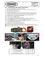
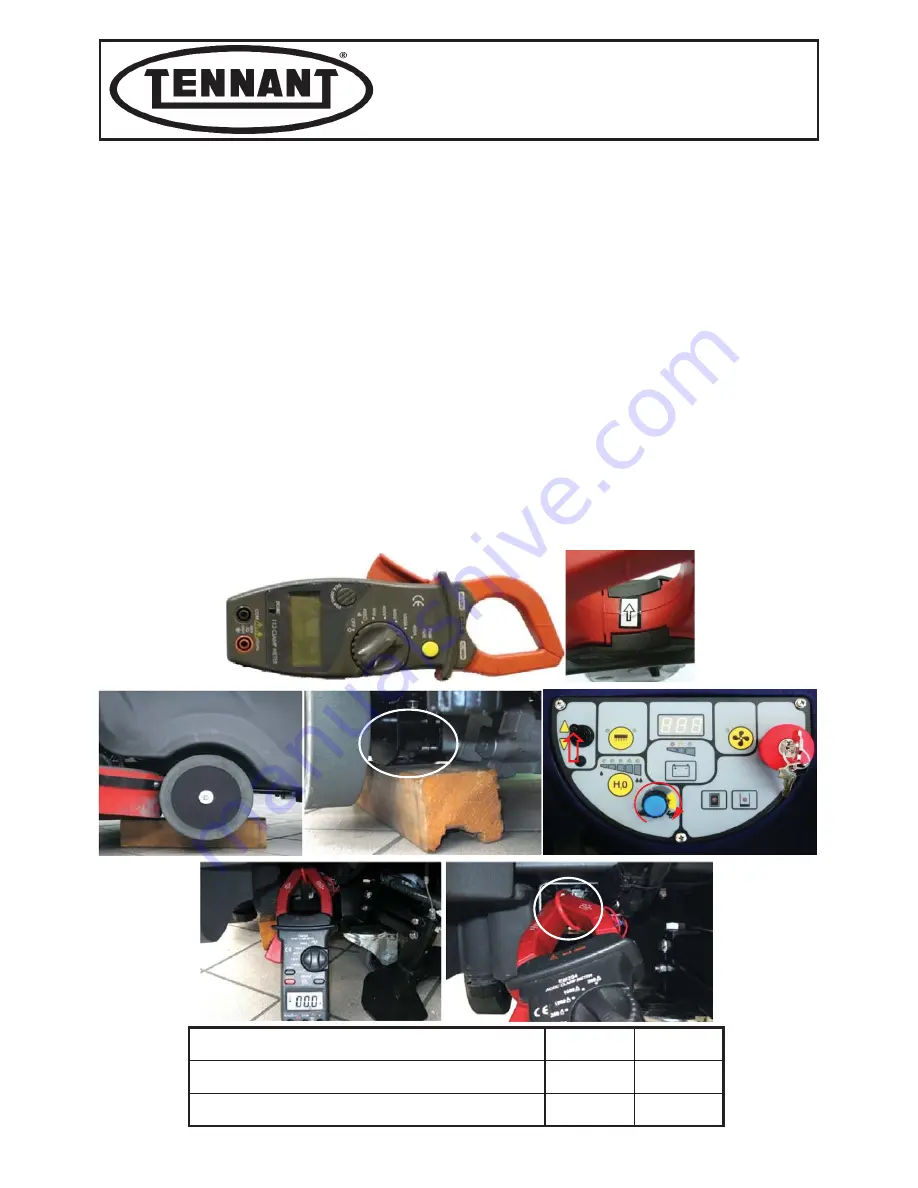
Use a clamp-on ammeter with a full scale reading of at least 200 amperes, as shown in Figure 339.
7
Lift the drive wheels, at least one of them, a few centimetres to check the current draw with no load.
8
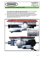
Identify the drive relay located under the chassis, at the rear, on the right near the solenoid valve
9
Identify the red wire on the drive board connected to the drive relay, see paragraph C 4.2.
10
Connect the clamp to the red wire as shown in Figure 341.
11
Switch the ammeter to
Amperes
and
DC
12
Turn the ignition key on the emergency switch clockwise.
13
Turn the speed controller on the instrument panel completely clockwise, see Figure 340.
14
Select forwards gear using the button on the instrument panel and press the enable brush lever.
15
Read the
CURRENT
with the motor at no load (without the machine operating).
16
Lower the wheels back to the ground and read the
CURRENT
with the machine in drive, with the tanks
empty, the brush lifted and all the functions off.
17
Compare the values measured against the chart below
18
If all the values are normal, remove the clamp-on ammeter.
19
If the values do not correspond to those specified (higher):
19a
Check that the reduction unit is intact and that there is nothing to impede the rotation of the wheels.
19b
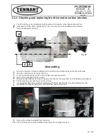
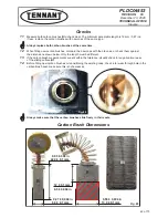
Check the condition of the motor carbon brushes, and then make sure the rotor turns freely, see par. C2.10.
19c
Replace the complete reduction unit.
C2.1 Checking the drive motor current draw
Current draw A (amperes)
Min
Max
No-load (wheel raised)
2.0 A
2.5 A
Load (on the floor, drive only)
6.0 A
10.0 A
Fig. 83
Fig. 85
Fig. 84
40 of 73

