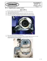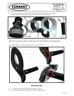
PLDC04453
REVISION 00
December 23, 2020
TECHNICAL OFFICE
Stavale
1
Empty the solution tank and the dirty water tank.
2
Bring to zero the amount of water dispensed.
3
Move the machine onto flat dry and smooth flooring.
4
Press the emergency switch to switch off all the functions.
5
Make sure that the batteries on the machine are charged.
6
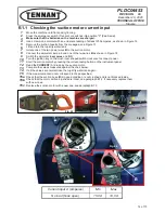
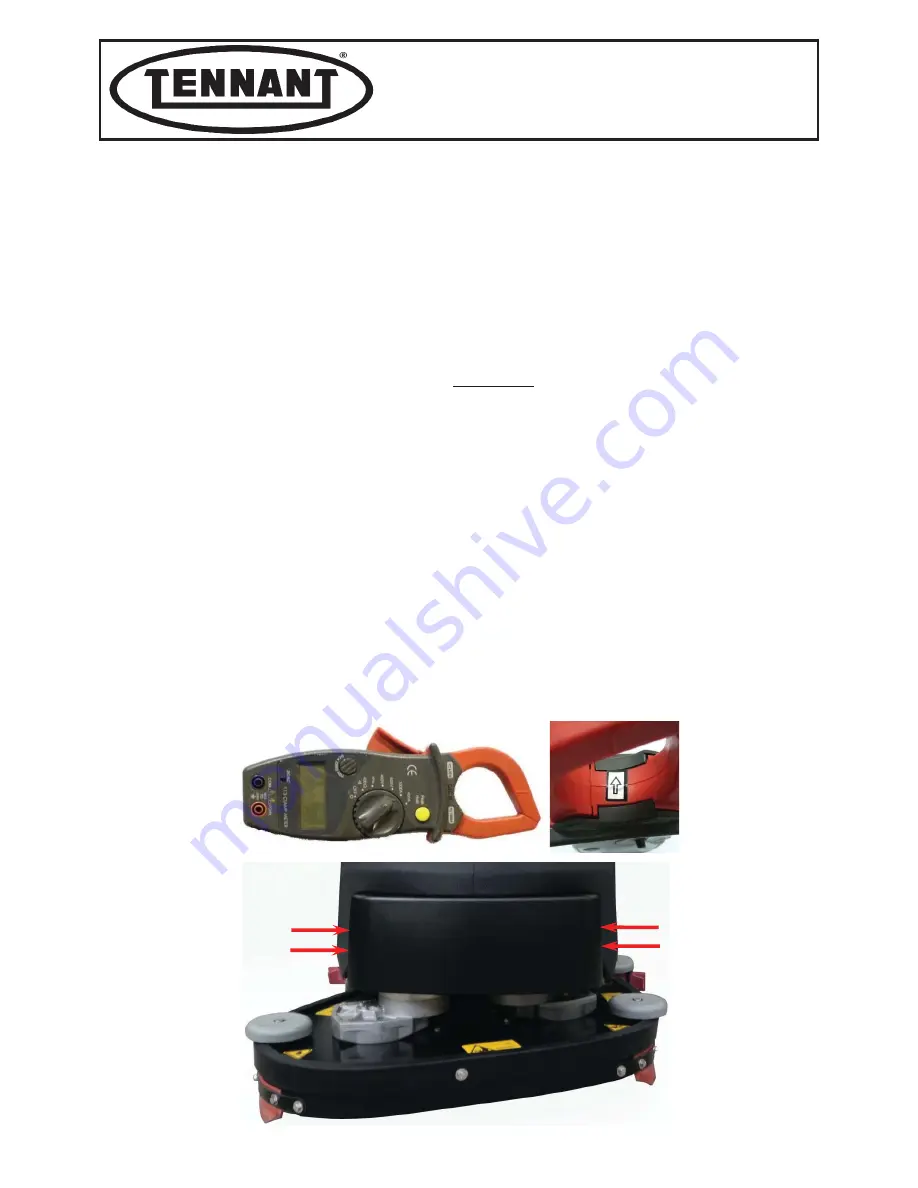
Use a clamp-on ammeter with an end scale reading of at least 200 amperes, as shown in Figure 1.
7
Remove the brush head cover.
8
Lift one of the machine’s two drive wheels, see paragraph C 2.1.
9
Move the speed knob on the instrument panel to zero, turning it anticlockwise.
10
Remove the brush head cover, unscrewing the four screw.
11
Switch the ammeter to
amperes
and
DC.
CHECKING POWER INPUT FOR EACH INDIVIDUAL MOTOR
Alternatively, electrically disconnect one motor, and then check the power input of the
other motor, both at no load and when working.
Checking the current with no load, i.e. without brushes.
12
Remove the brushes and lower the head using the special pedal control.
13
Turn the emergency button clockwise.
14
Press the button on the instrument panel to activate the brushes.
15
Controlling the rotation of the brushes using the drive lever, read the
CURRENT (A)
drawn by the brush reduction drive; for practicality, hold the lever in place with string.
16
Note down the value read, and then run the following check.
Checking the current in operation, i.e. with the brushes.
17
Replace the brushes on the reduction drive, and lower the brush head to the floor.
18
Repeat the readings, as described above.
19
Compare the values measured against the chart below.
20
If the values are OK, replace the brush motor cover.
21
If the values do not correspond to those specified (higher):
21a
Check that the brush drive (and thus the motor) is free to rotate, without interference.
21b
Check the power supply
VOLTAGE (V)
directly on the poles of the motor.
21c
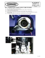
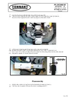
Check that the motor carbon brushes are intact, replace if necessary.
21d
Replace the defective motor or motors.
A1.1 Checking current input
Fig. 2
Fig. 3
3 of 73


